Introduction
The ESP32 and ESP8266 microcontrollers have significantly impacted the DIY electronics and IoT landscape due to their cost-effectiveness, versatility, and built-in Wi-Fi. These features make them ideal for numerous applications, one of the most intriguing being their ability to create web servers for remote device control. This capability allows users to automate and manage electrical devices from afar. In this tutorial, we will explore the steps to set up an ESP32 or ESP8266 as a web server to control a relay. The relay acts as an intermediary switch, enabling the control of high-power devices with low-power signals. This project combines web server setup, web interface design, relay control coding, and hardware connection, providing a comprehensive guide for remote device management using these powerful microcontrollers.T
Why to use ESP ?
he ESP32 and ESP8266 microcontrollers have significantly impacted the DIY electronics and IoT landscape due to their cost-effectiveness, versatility, and built-in Wi-Fi. These features make them ideal for numerous applications, one of the most intriguing being their ability to create web servers for remote device control. This capability allows users to automate and manage electrical devices from remote area. In this tutorial, we will explore the steps to set up an ESP32 or ESP8266 as a web server to control a relay. The relay acts as an intermediary switch, enabling the control of high-power devices with low-power signals. This project combines web server setup, web interface design, relay control coding, and hardware connection, providing a comprehensive guide for remote device management using these powerful microcontrollers.
Key Points:
- Cost-Effectiveness and Versatility: The ESP32 and ESP8266 are popular because they are affordable and versatile. They are suitable for a wide range of applications due to their robust feature set.
- Built-In Wi-Fi: The integrated Wi-Fi capability makes these microcontrollers ideal for IoT projects. This feature enables them to connect to the internet and be controlled remotely, which is a significant advantage for automation and remote monitoring tasks.
- Web Server Setup: By setting up the ESP32 or ESP8266 as a web server, you can control devices from a web interface. This involves configuring the microcontroller to serve web pages that allow user interaction, such as turning a relay on or off.
- Relay Control: A relay is used to control high-power devices with the low-power signals from the microcontroller. This is essential for safely switching devices that require more power than the microcontroller can provide directly.
- Comprehensive Project: The project involves several steps, including:
- Web Server Setup: Configuring the microcontroller to act as a web server.
- Web Interface Design: Creating a user-friendly interface for controlling the relay.
- Relay Control Coding: Writing the code to manage the relay based on web interface inputs.
- Hardware Connection: Connecting the relay to the microcontroller and the device you wish to control.
Project Overview
In this project, we will create a web server using the ESP32 or ESP8266 that can control a relay. By doing so, we can remotely switch devices on and off using a web browser. The project involves several key components:
- Setting Up the Web Server: Configure the ESP32/ESP8266 to serve web pages.
- Web Interface: Design a simple web interface that allows users to interact with the relay.
- Controlling the Relay: Write code to control the relay based on user input from the web interface.
- Connecting the Hardware: Properly connect the relay to the microcontroller and the device being controlled.
This project not only provides a practical solution for remote device control but also serves as an excellent learning experience for understanding web server concepts, interfacing with relays, and working with ESP32/ESP8266 microcontrollers. Whether you are a hobbyist looking to automate your home or a professional developing an IoT solution, this tutorial will provide you with the foundational knowledge to get started.
Hardware Requirements
Notice: There might be affiliate links to Amazon on this page. which implies that I may receive a tiny commission from the sale. This may be your way of indirectly assisting me. RegardsThese components are essential for building the authentication system. Using the affiliate links helps support my work, allowing me to continue creating valuable tutorials.
Software Requirements
ESP Board Manager
The ESP32/ESP Board Manager in Arduino IDE simplifies the development process for ESP32/ESP based projects. By installing the ESP32/ESP board manager, users can program and upload code to ESP32/ESP microcontrollers using the familiar Arduino environment. This integration provides access to a wide range of libraries and examples specifically tailored for the ESP32/ESP, enhancing functionality for IoT, Wi-Fi, and Bluetooth projects. The board manager also ensures that the necessary tools, drivers, and configurations are automatically set up, allowing developers to focus on coding and prototyping rather than setup issues. This makes the ESP32/ESP a powerful and versatile choice for embedded development. Follow the Tutorial and Know More
Why Use ESP32/ESP8266?
Both the ESP32 and ESP8266 are popular choices among hobbyists and professionals for building IoT solutions. Here are a few reasons why:
- Cost-Effective: These microcontrollers are inexpensive compared to other Wi-Fi-enabled devices, making them accessible for many applications.
- Built-In Wi-Fi: They come with integrated Wi-Fi modules, which eliminate the need for external networking hardware.
- Flexibility: Both boards support a variety of programming environments, including Arduino IDE, MicroPython, and PlatformIO, offering flexibility in development.
- Community Support: A large and active community provides a wealth of resources, tutorials, and libraries that make development easier.
What is a Relay?
A relay is an electrically operated switch that allows you to control a high-power device with a low-power signal. It can isolate different parts of a circuit and is commonly used to control appliances, lights, and other electrical equipment. In this project, the relay will act as an intermediary between the microcontroller and the device you wish to control.
How Relay Works?
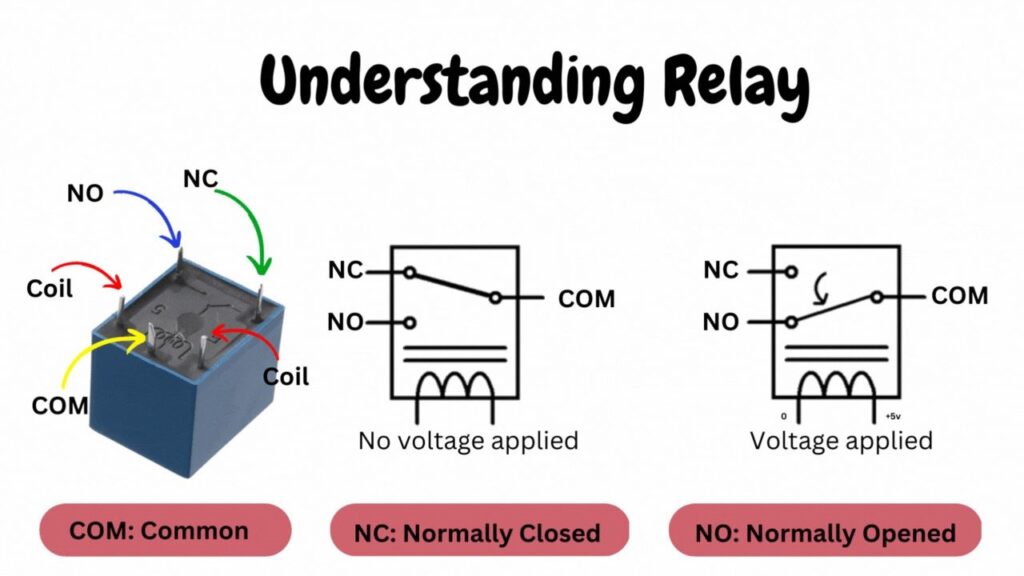
An SPDT (Single Pole Double Throw) relay is an electromechanical switch that connects one circuit to one of two other circuits. Here’s how it works:
Components of an SPDT Relay
- Electromagnet: A coil of wire that, when energized, creates a magnetic field.
- Armature: A movable metal arm that is attracted by the electromagnet when it is energized.
- Common Terminal (COM): The terminal that connects to the armature and moves between two other terminals.
- Normally Closed Terminal (NC): The NC terminal connects to the COM terminal when the relay coil is not energized, ensuring a default closed circuit.
- Normally Open Terminal (NO): The NO terminal connects to the COM terminal when the relay coil is energized, creating an open circuit by default that closes when powered.
- Coil: The coil returns the armature to its original position when the electromagnet is not energized, maintaining the default state of the relay.
Optimize your relay setup with these key components: the Normally Closed (NC) terminal, the Normally Open (NO) terminal, and the essential spring mechanism. Understanding how the NC terminal and NO terminal function in relation to the relay coil can significantly enhance your electronic projects. The spring’s role in resetting the armature ensures reliable operation in various applications.
Operation of an SPDT Relay
De-energized State:
- In its default state (when no current flows through the coil), a spring holds the armature against the NC terminal.
- The COM terminal connects to the NC terminal.
- Any circuit connected to the COM terminal connects to the NC terminal, allowing current to flow through this path.
Energized State:
- When a current flows through the coil, the electromagnet generates a magnetic field.
- This magnetic field attracts the armature, pulling it away from the NC terminal and towards the NO terminal.
- The COM terminal now connects to the NO terminal.
- Any circuit connected to the COM terminal now connects to the NO terminal, allowing current to flow through this new path.
Bootstrap
Bootstrap is a popular front-end framework for building responsive and visually appealing websites quickly. It provides a collection of pre-designed components, such as buttons, forms, navigation bars, and modals, along with a powerful grid system to create flexible layouts. Bootstrap’s responsive design features ensure that web pages look good on all devices, from desktops to smartphones. It includes utility classes that allow for quick styling and customization of elements. By using Bootstrap, developers can save time and effort as they don’t need to write all the CSS and JavaScript from scratch. The framework also ensures a consistent look and feel across different browsers and devices, enhancing user experience. Overall, Bootstrap is an essential tool for web developers to efficiently create modern and professional websites. Follow the Tutorial and Know More
Circuit Diagram
Circuit Explanation
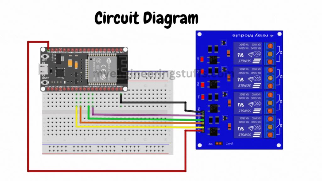
Relay Driver Circuit with ESP32
In this setup, we are using a 5V 4-channel relay driver to control up to four devices with an ESP32. Here is an explanation of the circuit and how it is connected:
Components
- ESP32: A microcontroller with built-in Wi-Fi and Bluetooth, acting as the main control unit.
- 5V 4-Channel Relay Driver: A module that can control up to four high-power devices using low-power signals from the ESP32.
Circuit Connections
| Relay Driver Pin | ESP32 Pin |
|---|---|
| VCC | 5V |
| GND | GND |
| IN1 | GPIO16 |
| IN2 | GPIO17 |
| IN3 | GPIO18 |
| IN4 | GPIO19 |
Explanation
- Power Connections:
- VCC to 5V: Connect the VCC pin of the relay driver to the 5V pin of the ESP32. This provides power to the relay module.
- GND to GND: Connect the GND pin of the relay driver to a GND pin on the ESP32. This ensures a common ground for both the relay driver and the ESP32.
- Control Connections:
- IN1 to GPIO16: Connect the IN1 pin of the relay driver to GPIO16 on the ESP32. This pin will control the first relay.
- IN2 to GPIO17: Connect the IN2 pin of the relay driver to GPIO17 on the ESP32. This pin will control the second relay.
- IN3 to GPIO18: Connect the IN3 pin of the relay driver to GPIO18 on the ESP32. This pin will control the third relay.
- IN4 to GPIO19: Connect the IN4 pin of the relay driver to GPIO19 on the ESP32. This pin will control the fourth relay.
Source Code
// Wi-Fi library
#include <WiFi.h>
// Replace with your network credentials
const char* SSID_NAME = "***********";
const char* SSID_PASSWORD = "*************";
// Set web server port number to 80
WiFiServer server(80);

// HTTP Header
String header;

//Variables to store the current output state
String relay16Status = "off";
String relay17Status = "off";
String relay18Status = "off";
String relay19Status = "off";

// Output GPIO pins
const int relay16 = 16;
const int relay17 = 17;
const int relay18 = 18;
const int relay19 = 19;

// Current time
unsigned long currentTime = millis();
// Previous time
unsigned long previousTime = 0;

const long timeoutTime = 5000;

void setup() {
  Serial.begin(9600);
  pinMode(relay16, OUTPUT);
  pinMode(relay17, OUTPUT);
  pinMode(relay18, OUTPUT);
  pinMode(relay19, OUTPUT);
  // Turn off all devices by default
  digitalWrite(relay16, HIGH);
  digitalWrite(relay17, HIGH);
  digitalWrite(relay18, HIGH);
  digitalWrite(relay19, HIGH);
  // Connect to Wi-Fi network with SSID and password
  Serial.print("Connecting to ");
  Serial.println(SSID_NAME);
  WiFi.begin(SSID_NAME, SSID_PASSWORD);
  while (WiFi.status() != WL_CONNECTED) {
    delay(500);
    Serial.print(".");
  }

  Serial.println("");
  Serial.println("WiFi connected.");
  Serial.println("IP address: ");
  Serial.println(WiFi.localIP());
  server.begin();
}
void loop(){
  WiFiClient client = server.available();
  if (client) {
    currentTime = millis();
    previousTime = currentTime;
    Serial.println("client connected.");
    String clientData = "";
    while (client.connected() && currentTime - previousTime <= timeoutTime) {
      currentTime = millis();
      if (client.available()) {
        char c = client.read();
        Serial.write(c);
        header += c;
        if (c == '\n') {
          if (clientData.length() == 0) {
            client.println("HTTP/1.1 200 OK");
            client.println("Content-type:text/html");
            client.println("Connection: close");
            client.println();
            if (header.indexOf("GET /16/on") >= 0) {
              Serial.println("GPIO 16 on");
              relay16Status = "on";
              digitalWrite(relay16, LOW);
            } else if (header.indexOf("GET /16/off") >= 0) {
              Serial.println("GPIO 16 off");
              relay16Status = "off";
              digitalWrite(relay16, HIGH);
            } else if (header.indexOf("GET /17/on") >= 0) {
              Serial.println("GPIO 17 on");
              relay17Status = "on";
              digitalWrite(relay17, LOW);
            } else if (header.indexOf("GET /17/off") >= 0) {
              Serial.println("GPIO 17 off");
              relay17Status = "off";
              digitalWrite(relay17, HIGH);
            }else if (header.indexOf("GET /18/on") >= 0) {
              Serial.println("GPIO 18 on");
              relay18Status = "on";
              digitalWrite(relay18, LOW);
            } else if (header.indexOf("GET /18/off") >= 0) {
              Serial.println("GPIO 18 off");
              relay18Status = "off";
              digitalWrite(relay18, HIGH);
            } else if (header.indexOf("GET /19/on") >= 0) {
              Serial.println("GPIO 19 on");
              relay19Status = "on";
              digitalWrite(relay19, LOW);
            } else if (header.indexOf("GET /19/off") >= 0) {
              Serial.println("GPIO 19 off");
              relay19Status = "off";
              digitalWrite(relay19, HIGH);
            }
            client.println("<!DOCTYPE html><html>");
            client.println("<head><meta charset=\"utf-8\">");
            client.println("<meta name=\"viewport\" content=\"width=device-width, initial-scale=1\">");
            //<!-- Bootstrap CSS -->
            client.println("<link rel=\"stylesheet\" href=\"https://cdn.jsdelivr.net/npm/bootstrap@4.0.0/dist/css/bootstrap.min.css\">");
            client.println("<title>MyEngineeringStuffs, ESP32 Projects</title>");
            client.println("</head>");
            // Web Page Body
            client.println("<body><main role=\"main\"><section class=\"jumbotron text-center\">");
            client.println("<div class=\"container\"><h1 class=\"jumbotron-heading\">ESP32 Web Server Example</h1>");
            client.println("<p class=\"lead text-muted\">This is an example to create a web server using ESP32 and controlling relays.");
            client.println("Controlling relays means you can control or turn ON or OFF any device or devices connected with your ESP32 board over WIFI.</p>");
            if (relay16Status=="off") {
              client.println("<a href=\"/16/on\" class=\"btn btn-primary my-2\">ON Device 1</a>");
            } else {
              client.println("<a href=\"/16/off\" class=\"btn btn-primary my-2\">OFF Device 1</a>");
            }
            if (relay17Status=="off") {
              client.println("<a href=\"/17/on\" class=\"btn btn-primary my-2\">ON Device 2</a>");
            } else {
              client.println("<a href=\"/17/off\" class=\"btn btn-primary my-2\">OFF Device 2</a>");
            }
            if (relay18Status=="off") {
              client.println("<a href=\"/18/on\" class=\"btn btn-primary my-2\">ON Device 3</a>");
            } else {
              client.println("<a href=\"/18/off\" class=\"btn btn-primary my-2\">OFF Device 3</a>");
            }
            if (relay19Status=="off") {
              client.println("<a href=\"/19/on\" class=\"btn btn-primary my-2\">ON Device 4</a>");
            } else {
              client.println("<a href=\"/19/off\" class=\"btn btn-primary my-2\">OFF Device 4</a>");
            }
            client.println("</p></div></section></main>");
            client.println("<footer class=\"text-muted\"><div class=\"container\">");
            client.println("<p>ESP32 Web Server Example. Please download the source code from my blog.");
            client.println("<b>Download</b> link is in the video description in my YouTube channel or at the bottom of this");
            client.println("article.</p></div></footer>");
            client.println("</body></html>");
            // The HTTP response ends with another blank line
            client.println();
            // Break out of the while loop
            break;
          } else { // if you got a newline, then clear currentLine
            clientData = "";
          }
        } else if (c != '\r') {  // if you got anything else but a carriage return character,
          clientData += c;      // add it to the end of the currentLine
        }
      }
    }
    // Clear the header variable
    header = "";
    // Close the connection
    client.stop();
    Serial.println("Client disconnected.");
    Serial.println("");
  }
}