Introduction
Controlling AC voltage is crucial in many applications, from household appliances to industrial machinery. One effective method to achieve precise control is by using Zero Voltage Crossing (ZVC) detection. This technique minimizes electrical noise and improves efficiency by switching at the point where the AC waveform crosses zero voltage. In this project, we will design an Arduino-based AC voltage control system utilizing ZVC detection.
When we plot this kind of voltage versus time on a graph, it looks like a sine wave. This wave oscillates smoothly and periodically, rising and falling in a consistent pattern. The voltage provided in our homes often takes the form of a sine wave with a peak value of 220-240 volts and a frequency of 50 Hz. This means the voltage alternates between positive and negative peaks, completing one full cycle 50 times per second. The sine wave shape is crucial for the efficient operation of many electrical devices and appliances, providing a steady and predictable flow of electrical energy. The smooth transitions of the sine wave help reduce the likelihood of electrical noise and interference, which can harm sensitive electronic equipment. The peak value indicates the maximum voltage reached during each cycle, while the root mean square (RMS) value, typically around 230 volts, represents the effective voltage level that powers our devices. The 50 Hz frequency is standard in many parts of the world, ensuring compatibility and synchronization with the electrical infrastructure and appliances designed to operate at this frequency.
What is AC Voltage Controlling ?
Controlling AC voltage involves adjusting the power supplied to devices like single-phase AC motors or incandescent bulbs. This means we want to control the motor’s speed or the bulb’s brightness by managing the voltage. However, we can’t simply cut off the voltage to achieve this control.
To effectively manage the voltage, we need to detect the moment when the AC voltage reaches zero volts, known as the zero crossing point. This is because switching the voltage at the zero crossing point minimizes electrical noise and ensures smoother operation. Once we detect this zero crossing point, we can then control the voltage by switching it on and off at the appropriate times to achieve the desired power output.
To detect this zero crossing point, we use a device called a zero voltage crossing detector. This detector helps us identify the exact moment when the AC voltage waveform crosses the zero-volt line, enabling precise control over the voltage and, consequently, the operation of the connected devices.
What is Zero Crossing Detector ?
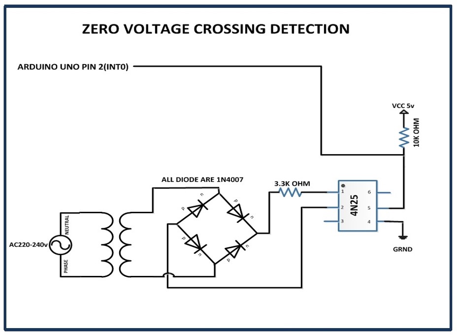
A Zero Crossing Detector (ZCD) is an circuit designed to detect the time at which the AC voltage signal crosses zero volt, follow the above diagram. This specific point, known as the zero crossing, is significant in many applications because it marks the transition of the AC signal from positive to negative voltage or vice versa. In an AC waveform, the voltage periodically changes direction, creating a sinusoidal pattern that oscillates above and below zero volts. Detecting the exact moment when the waveform passes through the zero-volt level is crucial for precise timing and control in various electronic systems.
In the context of power electronics, ZCDs play a vital role in phase control methods used to regulate the power delivered to loads. For instance, in a light dimmer circuit, the ZCD detects the zero crossing and signals the control circuitry to turn on or off a Triac or SCR at the appropriate time.
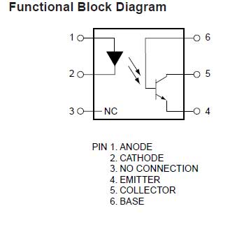
OPTOCOUPLER or OPTO ISOLATER( IC 4N25)
It consists of a phototransistor and an LED. The figure depicts its internal structure. Thus, the output at pin number 5 is LOW anytime the AC is at the appropriate voltage. Additionally, the LED on the IC turns off as it passes through the ZERO point, and pin 5 generates a HIGH pulse. Additionally, this HIGH pulse activates the interrupt (INT0) pin, turning on the circuit.
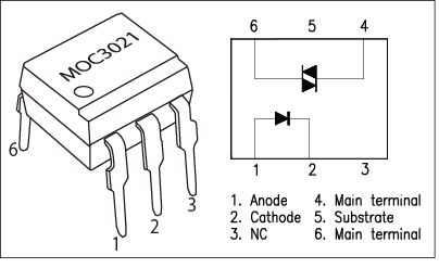
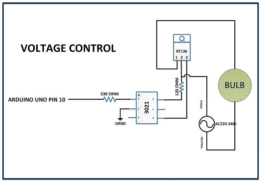
OPTOCOUPLER or OPTO ISOLATOR(MOC3021 IC)
In the image you can see that the internal circuit diagram.
The LED’s anode and cathode are located at pins 1 and 2, respectively.
The voltage at pin 1 determines the voltage across the thyristor and the brightness of the LED. Pins 4 and 6 trigger the gate pin of the TRIAC (BT136).
How a Zero Crossing Detector Works:
- Input Signal: The ZCD receives an AC input signal, which typically varies sinusoidally over time, oscillating between positive and negative voltage values.
- Detection: The ZCD monitors the input signal and detects the exact moment when the voltage crosses zero volts. This crossing point is referred to as the zero crossing.
- Output Signal: Upon detecting a zero crossing, the ZCD generates an output signal, usually a digital pulse or a square wave, that corresponds to the zero crossing events. This output signal can then be used to synchronize or trigger other circuits or devices.
TRIAC with Voltage Controlling
Hardware Required
Notice: There might be affiliate links to Amazon on this page. which implies that I may receive a tiny commission from the sale. This may be your way of indirectly assisting me. Regards- Arduino UNO (HERE)
- Alpha numeric 16×2 LCD (HERE)
- Bread Board for connection (HERE)
- MOC3021
- 1N4007 diode
- 4N25
- ON-OFF Switch
- Voltage regulator -7805
- BT136
- Wire to carry 2A,230v AC
- 12-0, 1amp Transformer
- Two-pin plug.
- Bulb holder
- PBT-2 terminal block
- 6-pin IC base-2pcs
- Resistors-10k, 3k3, 330, and 120 ohm
Software Requirements
- Arduino IDE
Block Diagram

Circuit Diagram
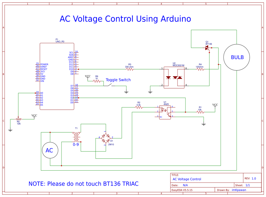
Circuit Explanation
- Arduino Board: The Arduino UNO used as the central controller of the circuit, managing all functionalities and interfacing with all modules.
- Power Supply: The Arduino UNO operates at 5V DC supply, and typically provided via a USB cable. For a standalone project you can use an external power supply with a 7805 voltage regulator can be used to provide a stable 5V.
- Variable Resistor: A variable resistor of 10K ohm is used to adjusts the firing angle. Were the one end is connected to GND, the other to VCC, and the middle/output pin to the A0 analog input of the Arduino UNO, allowing it to read varying voltage levels.
- Toggle Switch: A toggle switch controls the start and stop functions. It is connected to pin 7 of the Arduino UNO, with the other side connected to GND. When toggled, it grounds pin 7, allowing the Arduino to detect the switch state.
Source Code
#define triacPulse 10
#define SW 7

int x=0;
void setup(){
   pinMode(2, INPUT);
   digitalWrite(2, INPUT_PULLUP); // pull up
   pinMode(triacPulse, OUTPUT);
   pinMode(SW, INPUT);
   digitalWrite(SW, INPUT_PULLUP);
    }

void loop() {

  if (!digitalRead(SW)){ // When the switch is closed
    x=analogRead(A0);
    attachInterrupt(0, acon, FALLING); // attach Interrupt at PIN2
    }
  else if (digitalRead(SW)){
       detachInterrupt(0); // Detach Interrupt
     }
  }

void acon()
   {
    delayMicroseconds((analogRead(A0) * 7) + 200); // read AD0
    digitalWrite(triacPulse, HIGH);
    delayMicroseconds(50);  //delay 50 uSec on output pulse to turn on triac
    digitalWrite(triacPulse, LOW);
   }