Introduction
Home automation, which provides unmatched ease and control over household equipment, has emerged as a focus area for innovation in the rapidly developing field of smart technology. Since the introduction of microcontrollers such as the Raspberry Pi Pico, the potential for developing personalized home automation systems has increased significantly. This project investigates how to combine the Raspberry Pi Pico with Bluetooth technologies to create an affordable and effective home automation system.
The Raspberry Pi Pico is a powerful and small microcontroller that makes it the perfect foundation for creating a variety of home automation systems. Its Bluetooth functionality enables smooth wireless communication between a central control device and a variety of household gadgets. Through smartphones or other Bluetooth-enabled devices, people may easily control their home environment by utilizing Bluetooth.
About Project
The goal of this project is to show how to set up a home automation system utilising Bluetooth connectivity and a Raspberry Pi Pico step-by-step. We will go over the necessary parts, programming, and circuit design needed to enable remote control of household appliances. Whether you’re a tech enthusiast, hobbyist, or student, this book will provide you the skills and resources you need to set up your own smart home.
Come along with us as we set out to convert typical homes into smart homes, improving daily living by increasing connectivity, efficiency, and convenience. Now let’s explore the world of Raspberry Pi Pico-powered Bluetooth home automation!
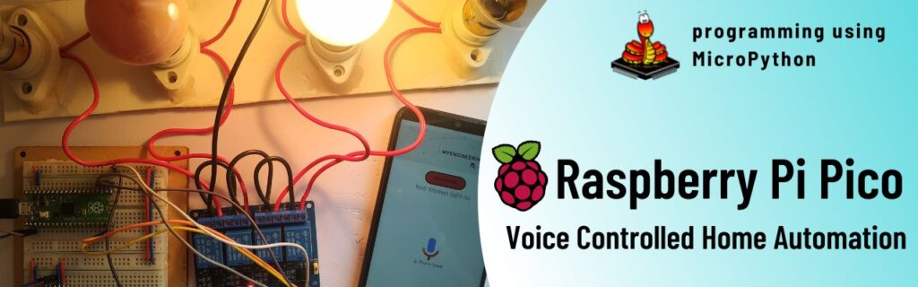
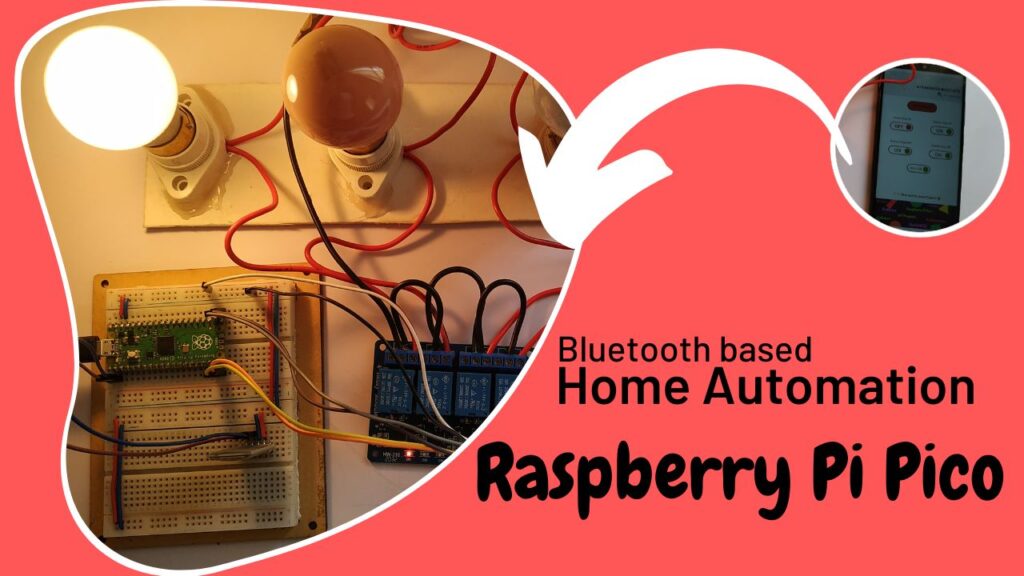
Together with an HC05 Bluetooth module, a 5V relay driver, and a Raspberry Pi Pico board, let’s build a home automation project. The remote control for each appliance will be an Android application.
For this project, I created an Android application, which you can download from the download area. You can follow the detailed instructions on my YouTube channel to learn how to construct the application. You can alternatively use my video instruction to develop your own mobile application if that’s more your style.
To finish this project, we’ll utilise MicroPython, a lightweight variant of Python optimised for low-memory devices. Now let’s get going.
Hardware Requirements
Notice: There might be affiliate links to Amazon on this page. which implies that I may receive a tiny commission from the sale. This may be your way of indirectly assisting me. Regards- Raspberry Pi Pico (HERE)
- Micro USB Cable (HERE)
- 4-Channel Relay Driver (HERE)
- HC05 Bluetooth Module (HERE)
- Connecting Wires (HERE)
- Breadboard (HERE)
- AC bulb holder
- AC bulb
- Connecting wire for AC lines
Software Requirements
About HC05 Bluetooth Module
Popular Bluetooth modules like the HC05 allow wireless communication between devices. This is a low-cost, compact module that connects to a computer or microcontroller via Bluetooth 2.0 technology, and it can also connect to a smartphone or tablet from a distance.
The module can support data transfer speeds of up to 2.1 Mbps and has a range of up to 8–10 metres. It supports several Bluetooth profiles, including the Serial Port Profile (SPP), which makes it simple to integrate with a variety of microcontrollers and other electronic devices. We can use in either slave or in master mode.
Popular Bluetooth modules like the HC05 allow wireless communication between devices. This is a low-cost, compact module that connects to a computer or microcontroller via Bluetooth 2.0 technology, and it can also connect to a smartphone or tablet from a distance.
The module can support data transfer speeds of up to 2.1 Mbps and has a range of up to 8–10 metres. It supports several Bluetooth profiles, including the Serial Port Profile (SPP), which makes it simple to integrate with a variety of microcontrollers and other electronic devices.
STDT 5v Relay
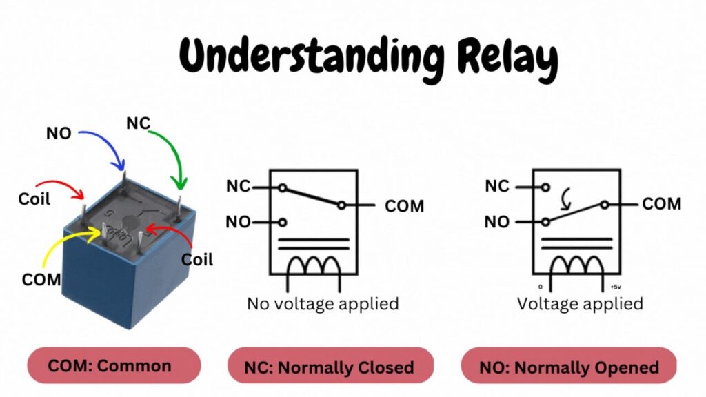
An electromechanical device called a 5V mechanical switching relay enables you to turn electrical circuits on or off with a low voltage control signal. It is made up of a coil, some contacts, and a switch that is turned on by the electromagnetic force the coil produces.
The contact connected at the NC ordinarily connected point shifts to the NO normally open point when the coil terminal receives the appropriate voltage. and finishing the entire circuit after that. Through an optocoupler in the 5v relay module, a digital signal is used to accomplish this mechanical switching.
Circuit Diagram
To guarantee that your circuit is assembled correctly, adhere to the circuit diagram.
Connect the HC-05 Bluetooth module in this way:
The Raspberry Pi Pico’s VCC, GND, and Tx modules are connected to the common 5V, GP0, and GP1 respectively. The Raspberry Pi Pico’s GND and Tx modules are connected to the common GND.
Concerning the 5V 4-channel relay relay driver:
| HC-05 Bluetooth | Raspberry Pi Pico |
| VCC | Common 5v |
| GND | Common GND |
| Tx | GP1 |
| Rx | GP0 |
Relay drivers for the following AC connections: VCC to Common 5V (Raspberry Pi Pico); GND to Common GND (Raspberry Pi Pico); IN1 to GP17 (Raspberry Pi Pico); IN2 to GP16 (Raspberry Pi Pico); IN3 to GP15 (Raspberry Pi Pico); and IN4 to GP14 (Raspberry Pi Pico).
| Relay Driver | Raspberry Pi Pico |
| VCC | Common 5v |
| GND | Common GND |
| IN1 | GP17 |
| IN2 | GP16 |
| IN4 | GP15 |
| IN4 | GP14 |
Source Code
from machine import Pin, UART
import utime

uart = UART(0,9600)
led = Pin(25, Pin.OUT)
realy1=Pin(14,Pin.OUT)
realy2=Pin(15,Pin.OUT)
realy3=Pin(16,Pin.OUT)
realy4=Pin(17,Pin.OUT)

message = ""
realy1.value(1)
realy2.value(1)
realy3.value(1)
realy4.value(1)
while True:
    print("waiting...")
    if uart.any():
        message = uart.readline()
        print(message)
        message= message.decode("utf-16")
        messages= str(message)
        print(messages)
        if messages =='*ON1#':
            realy1.value(0)
            print("got *ON1#")
        elif messages == '*OFF1#':
            realy1.value(1)
            print("got *OFF1#")
        elif messages == '*ON2#':
            realy2.value(0)
        elif messages =='*OFF2#':
            realy2.value(1)
        elif messages == '*ON3#':
            realy3.value(0)
        elif messages == '*OFF3#':
            realy3.value(1)
        elif messages == '*ON4#':
            realy4.value(0)
        elif messages == '*OFF4#':
            realy4.value(1)
        elif messages == '*ALLON#':
            realy1.value(0)
            realy2.value(0)
            realy3.value(0)
            realy4.value(0)
        elif messages == '*ALLOFF#':
            realy1.value(1)
            realy2.value(1)
            realy3.value(1)
            realy4.value(1)
    utime.sleep(0.5)
Source Code Explanation
MicroPython Code: This code written in the MicroPython programming language.
The main code is in (main.py).
In order to decide whether to turn on or off the devices connected to the relay, this last function receives data from the Bluetooth module, matches it to the data provided once more, and then activates accordingly. Open the Thonny IDE now, and add the code from the download section into a new file named BluetoothHomeAutomation.txt. Save this code as main.py to the Raspberry Pi Pico board.
What is the purpose of the file name main.py?
The file can have whatever name you choose, but the code will only run once when you click the green button to run it from the Thonny IDE. However, if we rename the file to main.py, the Raspberry Pi Pico board will recognize it and execute the code whenever you wish. You may refer to this as the system’s AutoStart procedure.