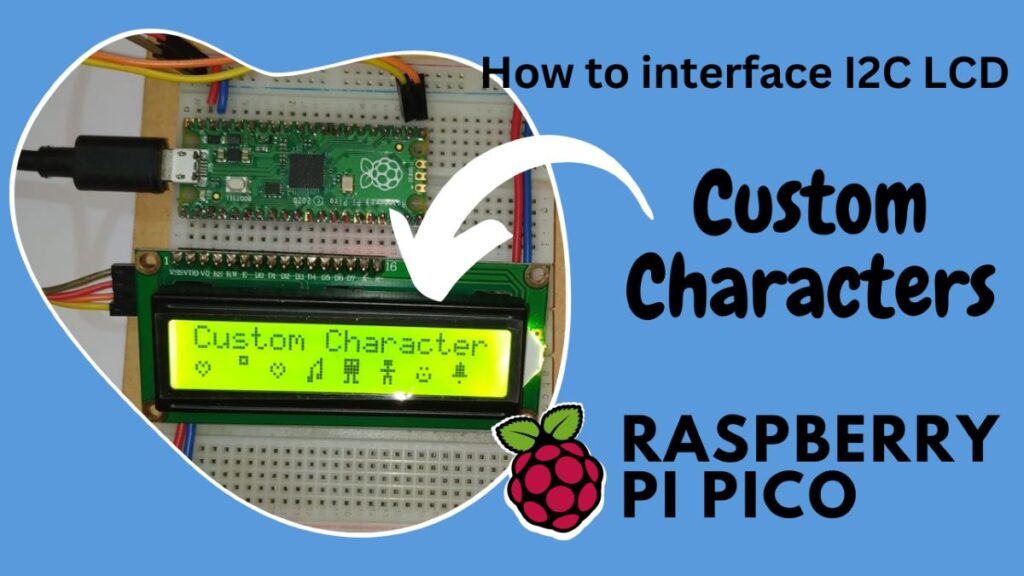
Introduction
This guide will teach you how to link a Raspberry Pi Pico board with an I2C alpha numeric 16×2 LCD. First, we will determine the I2C LCD address. Next, we will use a separate displaying command to display the LCD, and last, we will display the custom character.
The fundamental component of any device’s user interface is display text. Thus, the device must have an LCD to show user interface messages; however, if the number of GPIOs that can be interfaced with the device is limited, then the I2C protocol should be used.
Hardware Requirements
Disclaimer: It may contains Amazon affiliate links. which means I can get a small commission on the sale. This might be your indirect help to me. Thank You- Raspberry Pi Pico Board (HERE)
- Micro-USB Cable (HERE)
- I2C Module (HERE)
- 16×2 LCD Module (HERE)
- Small Breadboard (HERE)
- Connecting Wires (HERE)
Software Requirements
- Thonny IDE (Download HERE)
- findLCD code
- lcd api (LCD Library)
- pico_i2c_lcd (I2C LCD Library)
- LCD Test Code
- Custom Character Code (Download HERE)
Alphanumeric LCD
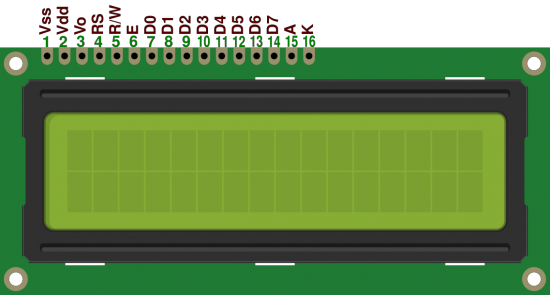
It is a rectangular LCD screen with two lines that can display up to 16 alphanumeric characters each. Its name, 16×2, comes from this. There are sixteen pins on it. A 16×2 LCD with corresponding pins is depicted in the diagram below.
By choosing command registers and transmitting the appropriate command instructions, we first initialise the LCD.
The second step is to choose data registers and send the corresponding data values for the display.
The data registers are D0 through D7, and the command registers are RS, RW, and EN.
PCF8574P I2C LCD Module
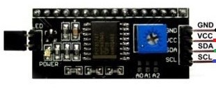
The silicon CMOS circuit PCF8574P IC. Using an I2C bus, it offers general-purpose I/O expansion for the majority of microcontroller families. The gadget has an I2C bus interface and an 8-bit quasi-bidirectional port. The integrated circuit exhibits low current consumption and latched outputs that can drive large current levels. Pin1, Pin2, and Pin 3 are the three addressing pins that are in charge of setting the address. To adjust the address to your specifications, go to the table below. The pin diagram for the I2C LCD module is shown in the image below.
Circuit Diagram
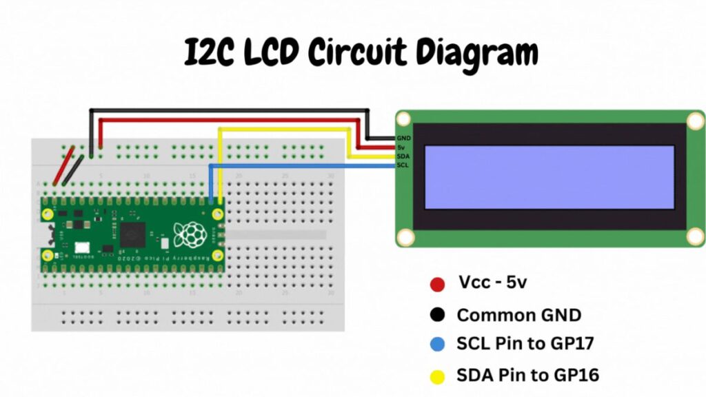
It only takes a few easy steps to create the wiring diagram needed to connect an I2C LCD to a Raspberry Pi Pico. Interfacing an LCD with the Pico is made possible by the I2C (Inter-Integrated Circuit) standard, which enables many devices to communicate using just two wires.
You can make a simple diagram that shows the Raspberry Pi Pico and the I2C LCD module with lines connecting the appropriate pins as stated to assist see the connections.
| I2C LCD | Raspberry Pi Pico |
| VCC | 5v |
| GND | Ground |
| SCL | GP17 |
| SDA | GP1 |
Source Code with Explanation
- findLCD code (Download HERE)
- lcd_api (LCD Library)
- pico_i2c_lcd (I2C LCD Library)
- LCD Test Code
- Custom Character Code (Download HERE)
pico_i2c_lcd library code:(pico_i2c_lcd.py)
Now, start a new file with the Thonny IDE. Copy the below code, and then paste it into the new file. On the Raspberry Pi Pico board, save this newly created file as pico_i2c_lcd.py. This is the I2C LCD library file and need to save it in the raspberry pi pico memory.
import utime
import gc

from lcd_api import LcdApi
from machine import I2C

# PCF8574 pin definitions
MASK_RS = 0x01       # P0
MASK_RW = 0x02       # P1
MASK_E  = 0x04       # P2

SHIFT_BACKLIGHT = 3  # P3
SHIFT_DATA      = 4  # P4-P7

class I2cLcd(LcdApi):

    #Implements a HD44780 character LCD connected via PCF8574 on I2C

    def __init__(self, i2c, i2c_addr, num_lines, num_columns):
        self.i2c = i2c
        self.i2c_addr = i2c_addr
        self.i2c.writeto(self.i2c_addr, bytes([0]))
        utime.sleep_ms(20)   # Allow LCD time to powerup
        # Send reset 3 times
        self.hal_write_init_nibble(self.LCD_FUNCTION_RESET)
        utime.sleep_ms(5)    # Need to delay at least 4.1 msec
        self.hal_write_init_nibble(self.LCD_FUNCTION_RESET)
        utime.sleep_ms(1)
        self.hal_write_init_nibble(self.LCD_FUNCTION_RESET)
        utime.sleep_ms(1)
        # Put LCD into 4-bit mode
        self.hal_write_init_nibble(self.LCD_FUNCTION)
        utime.sleep_ms(1)
        LcdApi.__init__(self, num_lines, num_columns)
        cmd = self.LCD_FUNCTION
        if num_lines > 1:
            cmd |= self.LCD_FUNCTION_2LINES
        self.hal_write_command(cmd)
        gc.collect()

    def hal_write_init_nibble(self, nibble):
        # Writes an initialization nibble to the LCD.
        # This particular function is only used during initialization.
        byte = ((nibble >> 4) & 0x0f) << SHIFT_DATA
        self.i2c.writeto(self.i2c_addr, bytes([byte | MASK_E]))
        self.i2c.writeto(self.i2c_addr, bytes([byte]))
        gc.collect()

    def hal_backlight_on(self):
        # Allows the hal layer to turn the backlight on
        self.i2c.writeto(self.i2c_addr, bytes([1 << SHIFT_BACKLIGHT]))
        gc.collect()

    def hal_backlight_off(self):
        #Allows the hal layer to turn the backlight off
        self.i2c.writeto(self.i2c_addr, bytes([0]))
        gc.collect()

    def hal_write_command(self, cmd):
        # Write a command to the LCD. Data is latched on the falling edge of E.
        byte = ((self.backlight << SHIFT_BACKLIGHT) |
                (((cmd >> 4) & 0x0f) << SHIFT_DATA))
        self.i2c.writeto(self.i2c_addr, bytes([byte | MASK_E]))
        self.i2c.writeto(self.i2c_addr, bytes([byte]))
        byte = ((self.backlight << SHIFT_BACKLIGHT) |
                ((cmd & 0x0f) << SHIFT_DATA))
        self.i2c.writeto(self.i2c_addr, bytes([byte | MASK_E]))
        self.i2c.writeto(self.i2c_addr, bytes([byte]))
        if cmd <= 3:
            # The home and clear commands require a worst case delay of 4.1 msec
            utime.sleep_ms(5)
        gc.collect()

    def hal_write_data(self, data):
        # Write data to the LCD. Data is latched on the falling edge of E.
        byte = (MASK_RS |
                (self.backlight << SHIFT_BACKLIGHT) |
                (((data >> 4) & 0x0f) << SHIFT_DATA))
        self.i2c.writeto(self.i2c_addr, bytes([byte | MASK_E]))
        self.i2c.writeto(self.i2c_addr, bytes([byte]))
        byte = (MASK_RS |
                (self.backlight << SHIFT_BACKLIGHT) |
                ((data & 0x0f) << SHIFT_DATA))
        self.i2c.writeto(self.i2c_addr, bytes([byte | MASK_E]))
        self.i2c.writeto(self.i2c_addr, bytes([byte]))
        gc.collect()
lcd_api library code:(lcd_api.py)
Now, open the Thonny IDE and make a new file. Copy the below code, and then paste it into the new one. Save this file to the Raspberry Pi Pico board as lcd_api.py. This is the LCD library file and need to save it in the raspberry pi pico memory.
import time

class LcdApi:
    # Implements the API for talking with HD44780 compatible character LCDs.
    # This class only knows what commands to send to the LCD, and not how to get
    # them to the LCD.
    #
    # It is expected that a derived class will implement the hal_xxx functions.
    #
    # The following constant names were lifted from the avrlib lcd.h header file,
    # with bit numbers changed to bit masks.

    # HD44780 LCD controller command set
    LCD_CLR             = 0x01  # DB0: clear display
    LCD_HOME            = 0x02  # DB1: return to home position

    LCD_ENTRY_MODE      = 0x04  # DB2: set entry mode
    LCD_ENTRY_INC       = 0x02  # DB1: increment
    LCD_ENTRY_SHIFT     = 0x01  # DB0: shift

    LCD_ON_CTRL         = 0x08  # DB3: turn lcd/cursor on
    LCD_ON_DISPLAY      = 0x04  # DB2: turn display on
    LCD_ON_CURSOR       = 0x02  # DB1: turn cursor on
    LCD_ON_BLINK        = 0x01  # DB0: blinking cursor

    LCD_MOVE            = 0x10  # DB4: move cursor/display
    LCD_MOVE_DISP       = 0x08  # DB3: move display (0-> move cursor)
    LCD_MOVE_RIGHT      = 0x04  # DB2: move right (0-> left)

    LCD_FUNCTION        = 0x20  # DB5: function set
    LCD_FUNCTION_8BIT   = 0x10  # DB4: set 8BIT mode (0->4BIT mode)
    LCD_FUNCTION_2LINES = 0x08  # DB3: two lines (0->one line)
    LCD_FUNCTION_10DOTS = 0x04  # DB2: 5x10 font (0->5x7 font)
    LCD_FUNCTION_RESET  = 0x30  # See "Initializing by Instruction" section

    LCD_CGRAM           = 0x40  # DB6: set CG RAM address
    LCD_DDRAM           = 0x80  # DB7: set DD RAM address

    LCD_RS_CMD          = 0
    LCD_RS_DATA         = 1

    LCD_RW_WRITE        = 0
    LCD_RW_READ         = 1

    def __init__(self, num_lines, num_columns):
        self.num_lines = num_lines
        if self.num_lines > 4:
            self.num_lines = 4
        self.num_columns = num_columns
        if self.num_columns > 40:
            self.num_columns = 40
        self.cursor_x = 0
        self.cursor_y = 0
        self.implied_newline = False
        self.backlight = True
        self.display_off()
        self.backlight_on()
        self.clear()
        self.hal_write_command(self.LCD_ENTRY_MODE | self.LCD_ENTRY_INC)
        self.hide_cursor()
        self.display_on()

    def clear(self):
        # Clears the LCD display and moves the cursor to the top left corner
        self.hal_write_command(self.LCD_CLR)
        self.hal_write_command(self.LCD_HOME)
        self.cursor_x = 0
        self.cursor_y = 0

    def show_cursor(self):
        # Causes the cursor to be made visible
        self.hal_write_command(self.LCD_ON_CTRL | self.LCD_ON_DISPLAY |
                               self.LCD_ON_CURSOR)

    def hide_cursor(self):
        # Causes the cursor to be hidden
        self.hal_write_command(self.LCD_ON_CTRL | self.LCD_ON_DISPLAY)

    def blink_cursor_on(self):
        # Turns on the cursor, and makes it blink
        self.hal_write_command(self.LCD_ON_CTRL | self.LCD_ON_DISPLAY |
                               self.LCD_ON_CURSOR | self.LCD_ON_BLINK)

    def blink_cursor_off(self):
        # Turns on the cursor, and makes it no blink (i.e. be solid)
        self.hal_write_command(self.LCD_ON_CTRL | self.LCD_ON_DISPLAY |
                               self.LCD_ON_CURSOR)

    def display_on(self):
        # Turns on (i.e. unblanks) the LCD
        self.hal_write_command(self.LCD_ON_CTRL | self.LCD_ON_DISPLAY)

    def display_off(self):
        # Turns off (i.e. blanks) the LCD
        self.hal_write_command(self.LCD_ON_CTRL)

    def backlight_on(self):
        # Turns the backlight on.

        # This isn't really an LCD command, but some modules have backlight
        # controls, so this allows the hal to pass through the command.
        self.backlight = True
        self.hal_backlight_on()

    def backlight_off(self):
        # Turns the backlight off.

        # This isn't really an LCD command, but some modules have backlight
        # controls, so this allows the hal to pass through the command.
        self.backlight = False
        self.hal_backlight_off()

    def move_to(self, cursor_x, cursor_y):
        # Moves the cursor position to the indicated position. The cursor
        # position is zero based (i.e. cursor_x == 0 indicates first column).
        self.cursor_x = cursor_x
        self.cursor_y = cursor_y
        addr = cursor_x & 0x3f
        if cursor_y & 1:
            addr += 0x40    # Lines 1 & 3 add 0x40
        if cursor_y & 2:    # Lines 2 & 3 add number of columns
            addr += self.num_columns
        self.hal_write_command(self.LCD_DDRAM | addr)

    def putchar(self, char):
        # Writes the indicated character to the LCD at the current cursor
        # position, and advances the cursor by one position.
        if char == '\n':
            if self.implied_newline:
                # self.implied_newline means we advanced due to a wraparound,
                # so if we get a newline right after that we ignore it.
                pass
            else:
                self.cursor_x = self.num_columns
        else:
            self.hal_write_data(ord(char))
            self.cursor_x += 1
        if self.cursor_x >= self.num_columns:
            self.cursor_x = 0
            self.cursor_y += 1
            self.implied_newline = (char != '\n')
        if self.cursor_y >= self.num_lines:
            self.cursor_y = 0
        self.move_to(self.cursor_x, self.cursor_y)

    def putstr(self, string):
        # Write the indicated string to the LCD at the current cursor
        # position and advances the cursor position appropriately.
        for char in string:
            self.putchar(char)

    def custom_char(self, location, charmap):
        # Write a character to one of the 8 CGRAM locations, available
        # as chr(0) through chr(7).
        location &= 0x7
        self.hal_write_command(self.LCD_CGRAM | (location << 3))
        self.hal_sleep_us(40)
        for i in range(8):
            self.hal_write_data(charmap[i])
            self.hal_sleep_us(40)
        self.move_to(self.cursor_x, self.cursor_y)

    def hal_backlight_on(self):
        # Allows the hal layer to turn the backlight on.
        # If desired, a derived HAL class will implement this function.
        pass

    def hal_backlight_off(self):
        # Allows the hal layer to turn the backlight off.
        # If desired, a derived HAL class will implement this function.
        pass

    def hal_write_command(self, cmd):
        # Write a command to the LCD.
        # It is expected that a derived HAL class will implement this function.
        raise NotImplementedError

    def hal_write_data(self, data):
        # Write data to the LCD.
        # It is expected that a derived HAL class will implement this function.
        raise NotImplementedError

    def hal_sleep_us(self, usecs):
        # Sleep for some time (given in microseconds)
        time.sleep_us(usecs)
findLCD code:
Now again create a new file, copy the below code, and save it to the Raspberry Pi Pico board as findLCD.py. When you run the file, the LCD’s address appears on the serial monitor. Need save the address of the I2C LCD will be use in the future.
import machine
sda = machine.Pin(16)
scl = machine.Pin(17)
i2cLCD = machine.I2C(0,sda=sda,scl=scl, freq=400000)
print(i2cLCD.scan())
Custom Character Code:
To show custom characters, copy the below entire code, and then create a new file in Thonny IDE. Paste the code, save it in a location of your choice, and execute it by clicking the green play button at the top of Thonny IDE.
from machine import Pin,  I2C
from lcd_api import LcdApi
from pico_i2c_lcd import I2cLcd
import utime

LCD_ADDR = 39
LCD_ROWS = 2
LCD_COLS = 16

i2c = I2C(0, sda=machine.Pin(16), scl=machine.Pin(17), freq=400000)
lcd = I2cLcd(i2c, LCD_ADDR, LCD_ROWS, LCD_COLS)

def welComeMessage():
    lcd.clear()
    lcd.move_to(5,0)
    lcd.putstr("Welcome")
    lcd.move_to(3,1)
    lcd.putstr("MyEngStuffs")
    utime.sleep(2)
    lcd.clear()


def customCharacters():
#heart fill
 lcd.custom_char(0, bytearray([
   0x00,
  0x00,
  0x0A,
  0xFF,
  0xFF,
  0x0E,
  0x04,
  0x00 ]))

#bell
 lcd.custom_char(7, bytearray([
    0x04,
  0x0E,
  0x0E,
  0x0E,
  0x1F,
  0x00,
  0x04,
  0x00]))

 #character
 lcd.custom_char(5, bytearray([
    0x0E,
  0x0E,
  0x04,
  0x1F,
  0x04,
  0x0E,
  0x0A,
  0x0A]))

 #character2
 lcd.custom_char(4, bytearray([
    0x1F,
  0x15,
  0x1F,
  0x1F,
  0x1F,
  0x0A,
  0x0A,
  0x1B]))
  #smiley
 lcd.custom_char(6, bytearray([
  0x00,
  0x00,
  0x0A,
  0x00,
  0x15,
  0x11,
  0x0E,
  0x00]))
  #heart
 lcd.custom_char(2, bytearray([
   0x00,
  0x00,
  0x0A,
  0x15,
  0x11,
  0x0A,
  0x04,
  0x00]))
 #note
 lcd.custom_char(3, bytearray([
   0x01,
  0x03,
  0x05,
  0x09,
  0x09,
  0x0B,
  0x1B,
  0x18 ]))
 #celcius
 lcd.custom_char(1, bytearray([
  0x07,
  0x05,
  0x07,
  0x00,
  0x00,
  0x00,
  0x00,
  0x00

      ]))
welComeMessage()
customCharacters()
lcd.move_to(0,0)
lcd.putstr("Custom Character")
lcd.move_to(0,1)
lcd.putchar(chr(0))
lcd.move_to(2,1)
lcd.putchar(chr(1))
lcd.move_to(4,1)
lcd.putchar(chr(2))
lcd.move_to(6,1)
lcd.putchar(chr(3))
lcd.move_to(8,1)
lcd.putchar(chr(4))
lcd.move_to(10,1)
lcd.putchar(chr(5))
lcd.move_to(12,1)
lcd.putchar(chr(6))
lcd.move_to(14,1)
lcd.putchar(chr(7))

while True:
    lcd.move_to(0,1)
    lcd.putchar(chr(0))
    utime.sleep(0.5)
    lcd.move_to(0,1)
    lcd.putchar(chr(2))
    utime.sleep(0.5)
You must save your script on the Raspberry Pi Pico board with the name main.py in order for it to start automatically. This is important because the Pico run’s a file called main.py automatically each time it boots up.