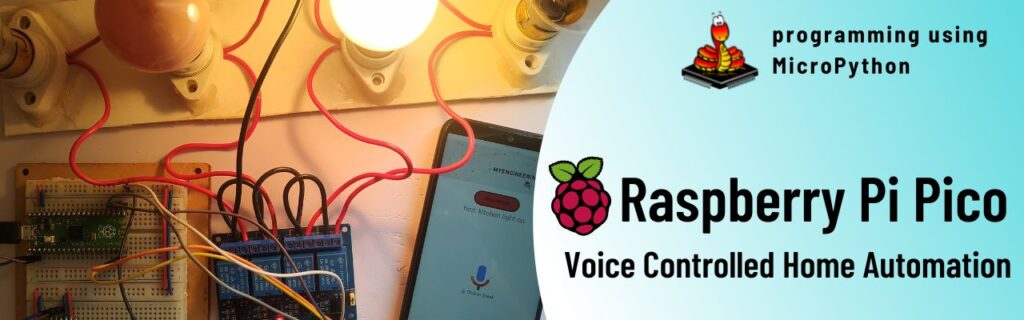
Introduction
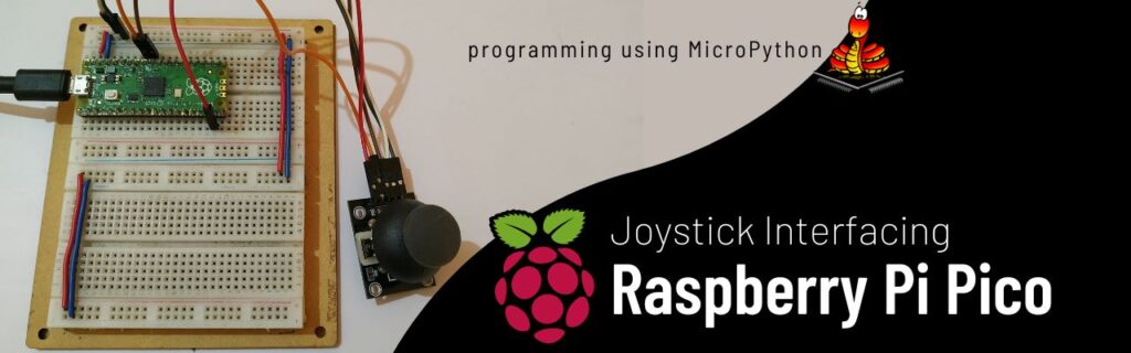
In this tutorial, we will learn how to interface a joystick module with a Raspberry Pi Pico board and observe the output. This project will demonstrate basic analog and digital input interfacing with the Raspberry Pi Pico. The joystick module has two potentiometers for reading the X and Y axis positions and a push-button switch for digital input. We’ll connect the X-axis to GP26, the Y-axis to GP27, and the push-button to GP22 on the Pico. Using MicroPython, we’ll read the analog values from the potentiometers and the digital state of the push-button, allowing us to control various tasks based on the joystick’s position and button press.
Components of the Joystick Module
The joystick module has two main components:
- Two Potentiometers: These are variable resistors used to measure the position of the joystick along two axes:
- X-axis: Moves left and right.
- Y-axis: Moves up and down.
- Push-button Switch: This is a button located in the middle of the joystick, which can be pressed to send a digital signal to the Raspberry Pi Pico.
Connections
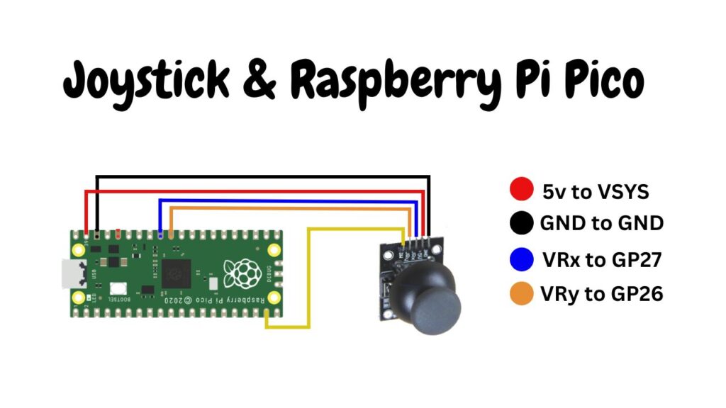
- X-axis Potentiometer: Connect to an analog input pin on the Raspberry Pi Pico (e.g., GP26).
- Y-axis Potentiometer: Connect to another analog input pin on the Raspberry Pi Pico (e.g., GP27).
- Push-button Switch: Connect to a digital input pin on the Raspberry Pi Pico (e.g., GP22).
How Joystick Works
- Analog Inputs: The potentiometers provide varying voltage levels as you move the joystick. The Raspberry Pi Pico reads these voltage levels using its analog-to-digital converter (ADC), which converts the analog signal (voltage) into a digital value that the Pico can process. These values represent the joystick’s position along the X and Y axes.
- Digital Input: When you press the push-button, it sends a digital signal (either HIGH or LOW) to the Raspberry Pi Pico. This can be used to trigger specific actions in your project.
Hardware Requirements
- Raspberry Pi Pico Board (HERE)
- Micro-USB Cable (HERE)
- PS2 Joystick (HERE)
- Small Breadboard (HERE)
- Connecting Wires (HERE)
Software Requirements
Circuit Diagram
Circuit Explanation
The above circuit diagram is straightforward and shows the direct connection of the PS2 joystick. Follow the connection table below to build the circuit:
This setup allows for easy interfacing of the joystick with the Raspberry Pi Pico.
| PS2 Joystick | Raspberry Pi Pico |
|---|---|
| VCC | 5V |
| GND | Ground |
| VRx | GP27 |
| VRy | GP26 |
| SW | GP14 |
Example Code
Here’s a simple code example to read the joystick’s position and the state of the push-button:
from machine import ADC, Pin
import time

# Initialize ADC pins for X and Y axes
x_axis = ADC(Pin(26))  # GP26
y_axis = ADC(Pin(27))  # GP27

# Initialize digital pin for the push-button
button = Pin(22, Pin.IN, Pin.PULL_DOWN)  # GP22

while True:
    x_value = x_axis.read_u16()  # Read X-axis position
    y_value = y_axis.read_u16()  # Read Y-axis position
    button_state = button.value()  # Read button state
    print("X-axis:", x_value, "Y-axis:", y_value, "Button:", button_state)
    time.sleep(0.1)  # Delay to make the readings more readable
Code Explanation
Initialization:
- x_axis = ADC(Pin(26)) and y_axis = ADC(Pin(27)) set up the pins for reading analog values from the X and Y potentiometers.
- button = Pin(22, Pin.IN, Pin.PULL_DOWN) sets up the pin for reading the digital state of the push-button, with a pull-down resistor to ensure a clear signal.
Reading Values:
- x_value = x_axis.read_u16() reads the X-axis position as a 16-bit digital value.
- y_value = y_axis.read_u16() reads the Y-axis position as a 16-bit digital value.
- button_state = button.value() reads the state of the push-button (1 if pressed, 0 if not).
Output:
- print(“X-axis:”, x_value, “Y-axis:”, y_value, “Button:”, button_state) prints the joystick’s X and Y positions and the button state to the console.
Loop:
- The while True loop continuously reads and prints the joystick’s position and button state, with a 0.1-second delay between readings for better readability.
Summary
By following these steps, you can interface a joystick module with your Raspberry Pi Pico and use it to control different tasks based on the joystick’s position and the push-button state. This project is an excellent way to learn about analog and digital inputs on the Raspberry Pi Pico.