Introduction
Security is a critical aspect of every project, and ensuring that only authorized individuals can access or control your system is essential. One of the most cost-effective and straightforward methods to add this layer of security is by using a keypad. By incorporating a keypad, you can implement password protection, providing an extra layer of security to your projects.
In this tutorial, we will guide you through the process of interfacing a keypad with an Arduino. You will learn how to connect the hardware components and write the necessary code to enable password protection. In this project, we will show how to turn on an LED , after we enter the correct password.
This tutorial is designed to help you integrate password protection into a variety of projects. Some practical applications include:
- Password Protected DC Motor Control: Control the operation of a DC motor by requiring a password to start or stop it.
- Password Protected Device Control: Securely manage the power to different devices, ensuring that only authorized users can turn them on or off.
- Door Lock System using Arduino: You can create an electronic door lock system, door opens when the correct password is entered, enhancing home or office security.
- Electronic Safe with Arduino: Build a safe that protects valuable items, which can only be accessed by entering the correct password.
By the end of this tutorial, you will have the knowledge and skills to implement password protection in your projects, making them more secure and reliable. Let’s get started and enhance your project’s security effectively and affordably!
Project Outline
In this project, we will integrate a 4×4 membrane keypad and display the value on an LCD screen. Following this, we will develop an authentication system project. In this system, we will check specific pairs of key combinations. Based on these key pairs, we will authenticate or unauthenticated the user for entry.
By the end of this project, you will have a comprehensive understanding of how to interface a keypad with an Arduino, display data on an LCD screen, and implement an authentication system to secure access based on specific key combinations. Let’s get started and enhance your project’s security effectively and affordably!
Hardware Requirements
Disclaimer: This section may contain Amazon affiliate links, which means I can earn a small commission on sales. Your support through these links is greatly appreciated. Thank you! 🙏- Arduino UNO (HERE)
- 4×4 Keypad (HERE)
- 16×2 LCD (HERE)
- I2C LCD Module (HERE)
- Small Breadboard (HERE)
- Connecting Wires (HERE)
These components are essential for building the authentication system. Using the affiliate links helps support my work, allowing me to continue creating valuable tutorials.
Software Requirements
- Arduino IDE
- Keypad Library
- I2C library
- Wire Library (inbuilt within the IDE)
Understanding 4×4 Membrane Keypad
A 4×4 membrane keypad is a user input device featuring a grid of 16 buttons arranged in four rows and four columns. Each button press connects a specific row to a specific column, creating a unique signal that the Arduino can detect. The keypad is composed of thin, flexible layers, making it durable and easy to integrate into various projects. The membrane keypad requires minimal power and has a compact design, making it ideal for applications with space constraints.
To interface the keypad with an Arduino, the rows and columns are connected to the digital pins of the microcontroller. Using the Keypad library, the Arduino can scan the rows and columns to identify which button is pressed. This functionality is crucial for creating password-protected systems, menu navigation, or other user input interfaces. The simplicity and reliability of the 4×4 membrane keypad make it a popular choice for hobbyists and professionals alike.
Block Diagram
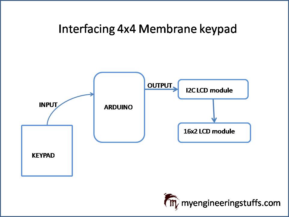
Explanation:
4×4 Membrane Keypad:
- Rows and Columns: The keypad consists of 4 rows and 4 columns. Each button press connects a specific row to a specific column.
- Connections: Connect each row and column wire to a digital I/O pin on the Arduino, as explained in the circuit section. Please refer to the table.
Arduino UNO:
- The keypad interfaces with the Arduino’s digital pins, typically using eight digital pins for the 4 rows and 4 columns.
- Keypad Library: The Arduino uses the Keypad library to scan the row and column lines to detect button presses.
16×2 LCD with I2C Module:
- I2C Module: The I2C module simplifies the connection to the Arduino by reducing the number of pins required to control the LCD. It uses the I2C communication protocol.
- Connections: The I2C module connects to the Arduino’s SDA and SCL pins (A4 and A5 on the Arduino UNO, respectively).
Power Supply:
The Arduino and all connected components receive power through a suitable power supply, typically via the Arduino’s USB connection or an external power adapter.
Connecting Wires:
Wires connect the keypad to the Arduino, and the LCD (via the I2C module) to the Arduino. Proper connections ensure the system functions correctly.
Circuit Diagram:
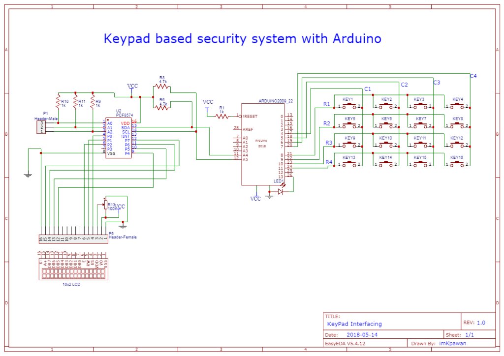
Circuit Explanation:
Connections for Columns (C1, C2, C3, C4):
| Keypad Column | Arduino UNO Digital Pin |
|---|---|
| C1 (Column 1) | 7 |
| C2 (Column 2) | 6 |
| C3 (Column 3) | 5 |
| C4 (Column 4) | 4 |
Connections for Rows (R1, R2, R3, R4):
| Keypad Row | Arduino UNO Digital Pin |
|---|---|
| R1 (Row 1) | 8 |
| R2 (Row 2) | 9 |
| R3 (Row 3) | 10 |
| R4 (Row 4) | 11 |
Interfacing the I2C LCD Module with Arduino UNO:
| I2C Module Pin | Arduino UNO Digital Pin |
|---|---|
| VCC | 5V |
| GND | GND |
| SDA (Data) | A4 (analog pin 4) |
| SCL (Clock) | A5 (analog pin 5) |
Circuit Overview:
Keypad Interface:
The keypad uses a matrix arrangement where columns (C1-C4) connect to output pins (4-7), and rows (R1-R4) connect to input pins (8-11) on the Arduino UNO. Follow the above table to build your own circuit.
The I2C LCD module simplifies wiring by using only two communication wires (SDA and SCL) for data transfer, reducing the complexity of connecting and controlling the LCD display. The VCC and GND of I2C LCD is connected to the 5v and GND of Arduino respectively.
This configuration enables effective integration of both the keypad for user input and the LCD display for output in Arduino projects, such as creating password-protected systems or interactive menu interfaces. Proper wiring and library usage ensure reliable communication and functionality between these components and the Arduino UNO microcontroller.
Interfacing Code
Interfacing-Code.txt
#include <Keypad.h>
#include <Wire.h>
#include <LiquidCrystal_I2C.h>
LiquidCrystal_I2C lcd(0x3F,16,2);
int i=0;
char customKey;
const byte ROWS = 4; //four rows
const byte COLS = 4; //four columns
//define the cymbols on the buttons of the keypads
char keys[ROWS][COLS] = {
  {'1','2','3','A'},
  {'4','5','6','B'},
  {'7','8','9','C'},
  {'*','0','#','D'}
};

byte rowPins[ROWS] = {11, 10, 9, 8}; //connect to the row pinouts of the keypad
byte colPins[COLS] = {7, 6, 5, 4}; //connect to the column pinouts of the keypad

Keypad customKeypad( makeKeymap(keys), rowPins, colPins, ROWS, COLS); //initialize an instance of class NewKeypad

void setup()
{
  lcd.begin();// initialize the lcd
  lcd.backlight();
  lcd.setCursor(0, 0);
  lcd.print(" Welcome to My  ");
  lcd.setCursor(0, 1);
  lcd.print(" YT Channel MES ");
  delay(3000);
  lcd.clear();
  delay(1000);
  lcd.setCursor(0, 0);
  lcd.print(" Press Any Key  ");
}


void loop()
{
  customKey = customKeypad.getKey();
  if(customKey){
  lcd.setCursor(i,1); // move cursor to show each new char
  lcd.print(customKey);
  delay(50);
  i++;
  }
}
Project Source Code
Password-Code.txt
#include <Keypad.h>
#include <Wire.h>
#include <LiquidCrystal_I2C.h>

#define Password_Lenght 5 // Give enough room for FOUR chars + NULL char

LiquidCrystal_I2C lcd(0x3F,16,2);
char Data[Password_Lenght]; // 4 is the number of chars it can hold + the null char = 5
char Master[Password_Lenght] = "5599";
byte data_count = 0, master_count = 0;
char customKey;

const byte ROWS = 4; //four rows
const byte COLS = 4; //four columns
//define the cymbols on the buttons of the keypads
char keys[ROWS][COLS] = {
  {'1','2','3','A'},
  {'4','5','6','B'},
  {'7','8','9','C'},
  {'*','0','#','D'}
};
byte rowPins[ROWS] = {11, 10, 9, 8}; //connect to the row pinouts of the keypad
byte colPins[COLS] = {7, 6, 5, 4}; //connect to the column pinouts of the keypad

Keypad customKeypad( makeKeymap(keys), rowPins, colPins, ROWS, COLS); //initialize an instance of class NewKeypad

void setup()
{
  lcd.begin();// initialize the lcd
  lcd.backlight();
  pinMode(13,OUTPUT);
  digitalWrite(13,LOW);
}

void loop()
{
  lcd.setCursor(0,0);
  lcd.print("Enter Password");
  customKey = customKeypad.getKey();
digitalWrite(13,LOW);
  delay(50);
  if (customKey) // makes sure a key is actually pressed, equal to (customKey != NO_KEY)
  {
    Data[data_count] = customKey; // store char into data array
    lcd.setCursor(data_count+3,1); // move cursor to show each new char
    lcd.print("*"); // print * in place of actual char at said cursor
    data_count++; // increment data array by 1 to store new char, also keep track of the number of chars entered
  }

  if(data_count == Password_Lenght-1) // if the array index is equal to the number of expected chars, compare data to master
  {
    lcd.clear();
    if(!strcmp(Data, Master)){ // equal to (strcmp(Data, Master) == 0)
       lcd.setCursor(0, 0);
       lcd.print(" Welcome to My  ");
       lcd.setCursor(0, 1);
       lcd.print(" YT Channel MES ");
       digitalWrite(13,HIGH);
    }
    else{
       lcd.setCursor(0, 0);
       lcd.print(" Access Denied  ");
       lcd.setCursor(0, 1);
       lcd.print("    SORRY!!!    ");
       digitalWrite(13,LOW);
      }
    delay(3000);// added 1 second delay to make sure the password is completely shown on screen before it gets cleared.
    lcd.clear();
    clearData();
  }
}

void clearData()
{
  while(data_count !=0)
  {   // This can be used for any array size,
    Data[data_count--] = 0; //clear array for new data
  }
  return;
}