Introduction
In this project, we will interface the Neo-6M GPS module with a NodeMCU to obtain real-time location data. We will cover every aspect of the project, including hardware setup, circuit design, and source code.
First, we will connect the Neo-6M GPS module to the NodeMCU, powering it with 3.3V and establishing a communication link using the TX pin of the GPS module and the RX pin (D7) and TX pin(D6) of the NodeMCU.
Next, we will install the required libraries: TinyGPS++ for parsing GPS data and SoftwareSerial for serial communication.
Finally, we’ll write an Arduino code to read GPS data and display it on the serial monitor. This sketch will initialize serial communication, read data from the GPS module, and print latitude, longitude, altitude, and other relevant information.
By following these steps, you will successfully capture and monitor real-time GPS data using the NodeMCU and Neo-6M GPS module.
Hardware Requirements
Disclaimer: It may contains Amazon affiliate links. which means I can get a small commission on the sale. This might be your indirect help to me. Thank You 🙏- NodeMCU (ESP8266) (Here)
- Neo-6M GPS Module (Here)
- Breadboard (Here)
- Jumper wires (Here)
- USB cable for programming the NodeMCU
Understanding the Neo-6M GPS Module
The Neo-6M GPS module is a popular GPS receiver that provides position, velocity, and time information. It communicates with the microcontroller using UART (Universal Asynchronous Receiver/Transmitter) protocol.
- VCC: Power supply (3.3V – 5V)
- GND: Ground
- TX: Transmit data (GPS data output)
- RX: Receive data (used for configuration, not needed for basic operation)
Circuit Diagram
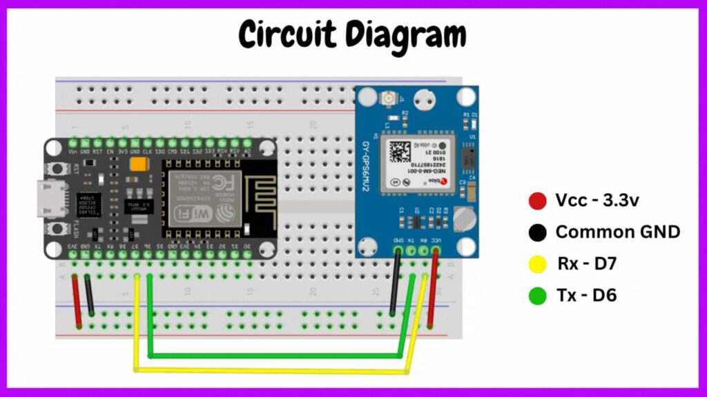
To interface the Neo-6M GPS module with the NodeMCU, we’ll connect the VCC and GND pins of the GPS module to the 3.3V and GND pins of the NodeMCU, respectively. The TX pin of the GPS module will be connected to the RX (D7) pin of the NodeMCU to receive the GPS data.
Setting Up the Software
Installing Required Libraries
We need to install the following libraries in the Arduino IDE:
- TinyGPS++ Library: To parse the GPS data.
- SoftwareSerial Library: To enable serial communication with the GPS module on the NodeMCU.
Steps to Install Libraries
- Open the Arduino IDE.
- Go to Sketch -> Include Library -> Manage Libraries.
- Search for TinyGPS++ and click Install.
- Search for SoftwareSerial and click Install.
Source Code
Know let’s write an Arduino sketch to read the GPS data from the Neo-6M module and print it to the serial monitor.
#include <SoftwareSerial.h>
#include <TinyGPS++.h>

// Create an instance of the TinyGPS++ object
TinyGPSPlus gps;

// Define the pins for SoftwareSerial
SoftwareSerial gpsSerial(D7, D6); // RX, TX

void setup() {
  // Start the hardware serial port for the NodeMCU
  Serial.begin(115200);
  // Start the software serial port for the GPS module
  gpsSerial.begin(9600);

  Serial.println("GPS module interface with NodeMCU");
}

void loop() {
  // This sketch displays information every time a new sentence is correctly encoded.
  while (gpsSerial.available() > 0) {
     gps.encode(gpsSerial.read());
    if (gps.location.isUpdated()) {
      Serial.print("Latitude: ");
      Serial.print(gps.location.lat(), 6);
      Serial.print(", Longitude: ");
      Serial.print(gps.location.lng(), 6);
      Serial.print(", Altitude: ");
      Serial.print(gps.altitude.meters());
      Serial.print(", Satellites: ");
      Serial.print(gps.satellites.value());
      Serial.print(", HDOP: ");
      Serial.println(gps.hdop.value());
    }
  }
}
Source Code Explanation
- Library Inclusions: We include the SoftwareSerial and TinyGPS++ libraries.
- Object Initialization: We create a TinyGPSPlus object and define the software serial pins.
- Setup Function:
- Initialize the hardware and software serial communications.
- Print a message to the serial monitor.
- Loop Function:
- Continuously read data from the GPS module.
- Decode the GPS data using the gps.encode() function.
- If the GPS location is updated, print the latitude, longitude, altitude, number of satellites, and HDOP (Horizontal Dilution of Precision) to the serial monitor.
Uploading the Code and Testing
- Connect the NodeMCU to your computer using the USB cable.
- Open the Arduino IDE and select the correct board and port under Tools.
- Upload the code to the NodeMCU.
- Open the Serial Monitor from the Arduino IDE to see the GPS data.
Conclusion
By following these steps, you have successfully interfaced the Neo-6M GPS module with the NodeMCU. You can now read and monitor real-time location data. This setup can be further extended to include other functionalities like displaying the data on an OLED screen or sending the data to an IoT platform for remote monitoring.
Pingback: How to Interface Membrane Matrix Keypad Using Arduino Uno with Example Project - Projects4u
Pingback: Home Automation Project Using Raspberry Pi Pico Bluetooth - Projects4u
Pingback: How to Interface P10 Display Using Arduino UNO - Projects4u
Pingback: Bluetooth Controlled Notice Board Using HC-05 and Arduino - Projects4u
Pingback: Smart Home Automation with Google Firebase and NodeMCU - Projects4u