Introduction
A P10 display in addition an Arduino Uno interface provides up a world of possibilities for projects that are colourful and visually appealing. P10 displays provide a reliable and adaptable way to show text, graphics, and animations. They are frequently used for digital displays and advertising boards. Beginning users may construct attractive displays for a variety of applications, from home automation to educational projects, by using the Arduino Uno’s power and simplicity.
In this tutorial we will teach you how to link an Arduino Uno with a P10 display. And you will learn how to make dynamic and captivating displays for your projects with our step-by-step tutorials, wiring schematics, and coding hints. Ideal for both novices and enthusiasts!
About P10 Display
A P10 display, known for its 10mm pixel pitch, is a versatile and bright LED module used in digital signage. Its modular design allows for scalable displays, suitable for both indoor and outdoor applications. P10 displays are durable, weatherproof, and can show text, images, and animations. They are easily controlled using microcontrollers like the Arduino Uno, making them popular for DIY projects, advertising, public information, and events. Available in single and full-color options, P10 displays provide high visibility and dynamic visual presentations, making them ideal for various creative and practical applications.
P10 Display Pin Descriptions:
- Pin 1 (OE): This enable pin controls the brightness of the panel.
- Pin 2 (A) and Pin 3 (B): These are selection lines used to choose from multiple rows.
- Pin 8 (CLK), Pin 10 (SCLK), and Pin 12 (DATA): These pins control the shift register.
Hardware Requirements
Notice: There might be affiliate links to Amazon on this page. which implies that I may receive a tiny commission from the sale. This may be your way of indirectly assisting me. RegardsSoftware Requirements
- Arduino IDE (You can download it from HERE)
- DMD Library
- TimerOne Library
Circuit Diagram
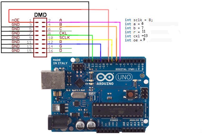
To create the proper circuit connections, please refer to the circuit diagram and the table below. Make sure an external 5V, 2Amp power supply powers the P10 display.
To connect the Arduino Uno and P10 display accurately, use the supplied circuit diagram and table.
A steady 5V power supply with a 2 Amp current rating is needed for the P10 display. The requirement cannot be fulfilled by the Arduino Uno alone; a separate power source is required.
To ensure the display works properly and no components are damaged, carefully follow the diagram and table to connect each pin correctly.
| P10 Display | Arduino UNO |
| PIN1 (OE) | D9 |
| PIN2 (A) and PIN3 (B) | D6 and D7 respectively |
| PIN8 (CLK) | D13 |
| PIN10 (SCLK) | D8 |
| PIN12 (DATA) | D11 |
Source Code
#include <SPI.h>        //SPI.h must be included as DMD is written by SPI (the IDE complains otherwise)
#include <DMD.h>        //
#include <TimerOne.h>   //
#include "SystemFont5x7.h"
#include "Arial_black_16.h"

//Fire up the DMD library as dmd
#define DISPLAYS_ACROSS 1
#define DISPLAYS_DOWN 1
DMD dmd(DISPLAYS_ACROSS, DISPLAYS_DOWN);

void ScanDMD()
{
  dmd.scanDisplayBySPI();
}

void setup(void)
{

   //initialize TimerOne's interrupt/CPU usage used to scan and refresh the display
Timer1.initialize( 5000 ); //period in microseconds to call ScanDMD. Anything longer than 5000 (5ms) and you can see flicker.
Timer1.attachInterrupt( ScanDMD );   //attach the Timer1 interrupt to ScanDMD which goes to dmd.scanDisplayBySPI()
//clear/init the DMD pixels held in RAM
dmd.clearScreen( true );   //true is normal (all pixels off), false is negative (all pixels on)
}

void loop(void)
{
   byte b;

   // 10 x 14 font clock, including demo of OR and NOR modes for pixels so that the flashing colon can be overlayed
   dmd.clearScreen( true );
   dmd.selectFont(Arial_Black_16);
   dmd.drawChar(  0,  3, '2', GRAPHICS_NORMAL );
   dmd.drawChar(  7,  3, '3', GRAPHICS_NORMAL );
   dmd.drawChar( 17,  3, '4', GRAPHICS_NORMAL );
   dmd.drawChar( 25,  3, '5', GRAPHICS_NORMAL );
   dmd.drawChar( 15,  3, ':', GRAPHICS_OR     );   // clock colon overlay on
   delay( 1000 );
   dmd.drawChar( 15,  3, ':', GRAPHICS_NOR    );   // clock colon overlay off
   delay( 1000 );
   dmd.drawChar( 15,  3, ':', GRAPHICS_OR     );   // clock colon overlay on
   delay( 1000 );
   dmd.drawChar( 15,  3, ':', GRAPHICS_NOR    );   // clock colon overlay off
   delay( 1000 );
   dmd.drawChar( 15,  3, ':', GRAPHICS_OR     );   // clock colon overlay on
   delay( 1000 );

   dmd.drawMarquee("Scrolling Text",14,(32*DISPLAYS_ACROSS)-1,0);
   long start=millis();
   long timer=start;
   boolean ret=false;
   while(!ret){
     if ((timer+30) < millis()) {
       ret=dmd.stepMarquee(-1,0);
       timer=millis();
     }
   }
   // half the pixels on
   dmd.drawTestPattern( PATTERN_ALT_0 );
   delay( 1000 );

   // the other half on
   dmd.drawTestPattern( PATTERN_ALT_1 );
   delay( 1000 );

   // display some text
   dmd.clearScreen( true );
   dmd.selectFont(System5x7);
   for (byte x=0;x<DISPLAYS_ACROSS;x++) {
     for (byte y=0;y<DISPLAYS_DOWN;y++) {
       dmd.drawString(  2+(32*x),  1+(16*y), "freet", 5, GRAPHICS_NORMAL );
       dmd.drawString(  2+(32*x),  9+(16*y), "ronic", 5, GRAPHICS_NORMAL );
     }
   }
   delay( 2000 );

   // draw a border rectangle around the outside of the display
   dmd.clearScreen( true );
   dmd.drawBox(  0,  0, (32*DISPLAYS_ACROSS)-1, (16*DISPLAYS_DOWN)-1, GRAPHICS_NORMAL );
   delay( 1000 );

   for (byte y=0;y<DISPLAYS_DOWN;y++) {
     for (byte x=0;x<DISPLAYS_ACROSS;x++) {
       // draw an X
       int ix=32*x;
       int iy=16*y;
       dmd.drawLine(  0+ix,  0+iy, 11+ix, 15+iy, GRAPHICS_NORMAL );
       dmd.drawLine(  0+ix, 15+iy, 11+ix,  0+iy, GRAPHICS_NORMAL );
       delay( 1000 );

       // draw a circle
       dmd.drawCircle( 16+ix,  8+iy,  5, GRAPHICS_NORMAL );
       delay( 1000 );

       // draw a filled box
       dmd.drawFilledBox( 24+ix, 3+iy, 29+ix, 13+iy, GRAPHICS_NORMAL );
       delay( 1000 );
     }
   }

   // stripe chaser
   for( b = 0 ; b < 20 ; b++ )
   {
      dmd.drawTestPattern( (b&1)+PATTERN_STRIPE_0 );
      delay( 200 );
   }
   delay( 200 );
}

Pingback: Bluetooth Controlled Notice Board Using HC-05 and Arduino - Projects4u