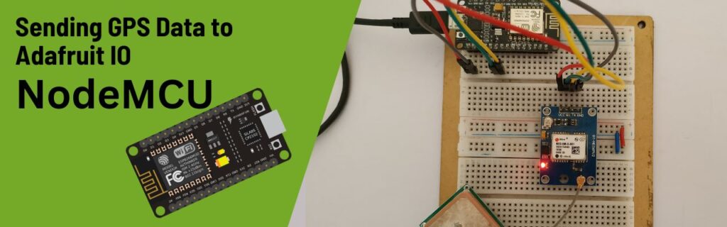
Introduction
In this tutorial, you will learn how to integrate a NodeMCU with a DHT11 sensor to collect temperature and humidity data, and then send this data to the Adafruit IO IoT platform for remote monitoring.
We will start by introducing the Adafruit IO platform, guiding you through the process of creating a free account. You’ll learn how to set up feeds to store your sensor data and create dashboards to visualize this data effectively.
On the hardware side, we will cover the steps to connect the DHT11 sensor to the NodeMCU. Additionally, we will install necessary libraries, such as the Adafruit MQTT Library and the DHT11 sensor library by Adafruit, to facilitate communication between the NodeMCU and Adafruit IO.
For those interested in enhancing their project, we will provide guidance on integrating an OLED display. You can follow our detailed OLED display tutorials on our blog and incorporate the provided code into this project for a more comprehensive display solution.
Why Ardafruit IO
Adafruit IO is a versatile Internet of Things (IoT) platform designed to help users collect, visualize, and analyze data from various sensors and devices. Developed by Adafruit Industries, it is particularly well-suited for hobbyists, makers, and students who are exploring the world of IoT and data-driven projects
Adafruit IO is an invaluable tool for students venturing into the world of IoT. Its ease of use, robust features, and supportive community make it an ideal platform for learning, experimenting, and innovating in the realm of connected devices. Whether it’s for a class project or a personal exploration, Adafruit IO equips students with the resources they need to succeed in their IoT journeys.
- Data Feeds: Adafruit IO allows users to create data feeds to store and manage sensor data. Each feed can handle different types of data, making it easy to organize and retrieve information.
- Dashboards: Users can create customizable dashboards to visualize data in real-time. With various widgets like charts, gauges, and maps, students can easily monitor their projects.
- Triggers: Adafruit IO supports triggers that can automate actions based on specific conditions. For example, students can set up alerts to notify them when sensor values exceed a certain threshold.
Benefits for Students
- Hands-on Learning: Adafruit IO offers a practical platform for students to apply theoretical concepts in real-world scenarios. By working on IoT projects, students can gain hands-on experience in electronics, programming, and data analytics.
- Simplified IoT Development: With its user-friendly interface and comprehensive documentation, Adafruit IO simplifies the development process, allowing students to focus on the creative aspects of their projects rather than getting bogged down by technical complexities.
- Visualization and Analysis: The platform’s powerful visualization tools help students understand their data better. They can identify trends, analyze patterns, and derive meaningful insights from their sensor data.
Hardware Requirements
Notice: There might be affiliate links to Amazon on this page. which implies that I may receive a tiny commission from the sale. This may be your way of indirectly assisting me. Regards- NodeMCU (ESP8266) (Here)
- Neo-6M GPS Module (Here)
- Breadboard (Here)
- Jumper wires (Here)
- USB cable for programming the NodeMCU
Adafruit IO account
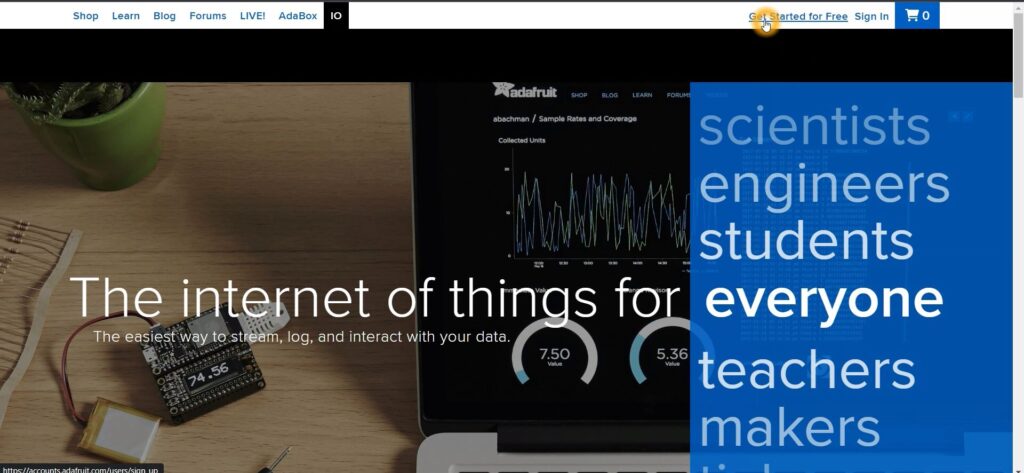
To start using Adafruit IO, you first need to create a free account. Here’s a detailed guide to help you through the process:
Visit the Official Adafruit IO Website: Open your web browser and navigate to the Adafruit IO website.
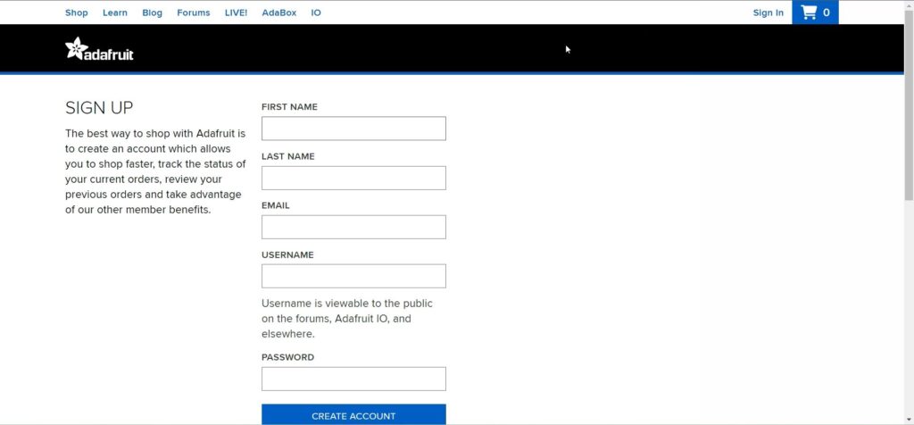
To create a free account, fill in the required details on the registration form. After entering your information, click on the “CREATE ACCOUNT” button to complete the process.
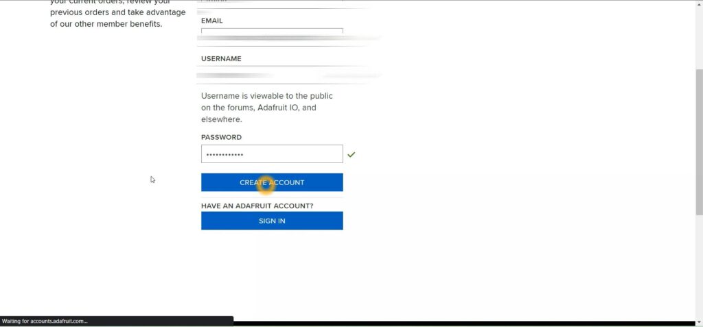
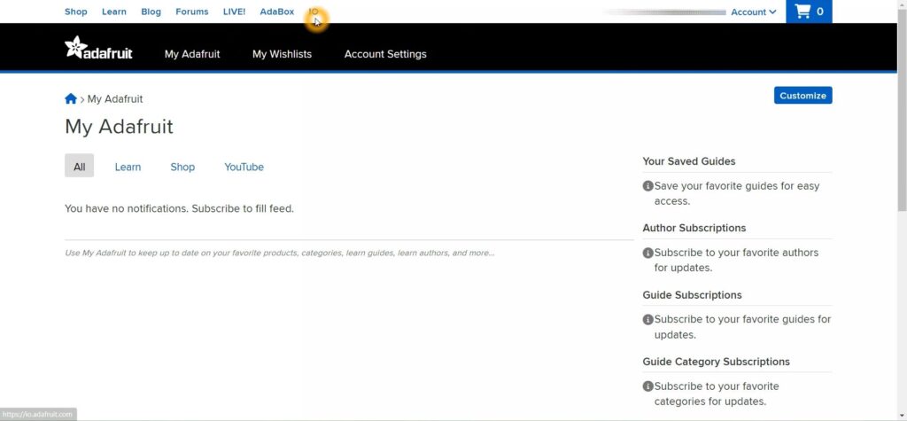
After clicking on “CREATE ACCOUNT,” your free account will be successfully created. Next, sign in to your account using your email and password. Once logged in, navigate to the top of the page and click on “IO” to access the Adafruit IO dashboard. Here, you can create a new dashboard and set up data feeds to display your location data collected from ESP. This will allow you to visualize and monitor the data in real-time.
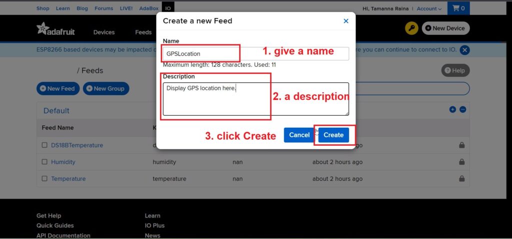
To create a feed, click on “Feeds” at the top of the Adafruit IO dashboard. A feed acts as a variable that you can subscribe to, allowing you to read from and write data to it. To set up a new feed, click on “Feeds” and then select “Create a New Feed.” A popup window will appear where you need to enter a name and a description for your feed. Once you’ve filled in these details, click “Create” to finalize the process. See below for reference
To create a dashboard, click on the “Dashboards” tab at the top of the Adafruit IO page. Similar to creating a feed, you will need to click on “Create Dashboard.” A popup window will appear, prompting you to enter details for your new dashboard, such as its name and description. After providing the required information, click “Create” to set up your dashboard. This dashboard will be used to visualize and monitor the data from your feeds in a user-friendly interface. Refer below image.
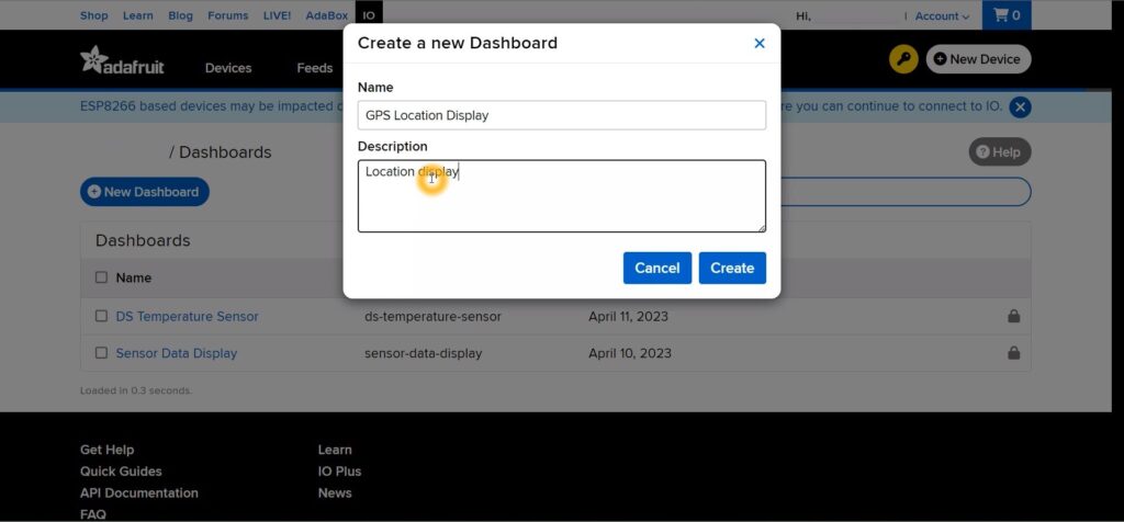
After creating a feed named “GPSLocation” and a dashboard named “GPS Location Display,” you need to link the feed to the dashboard to visualize the data.
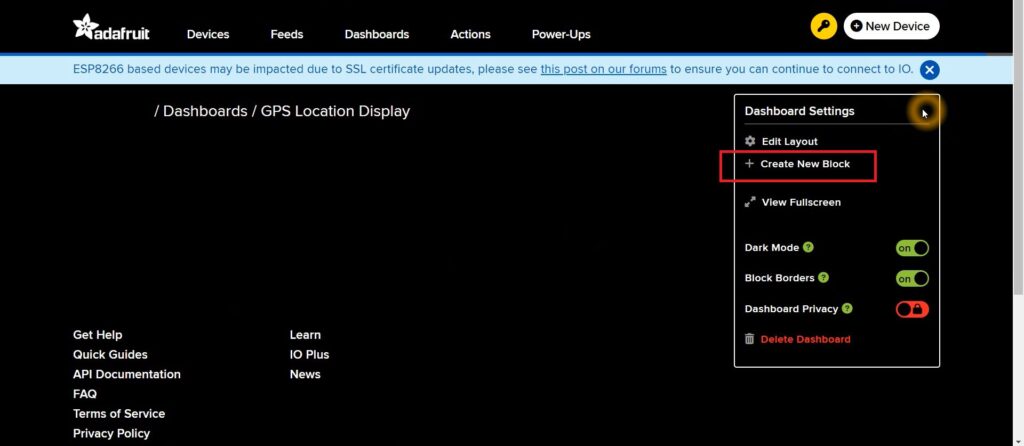
To connect the feed to the dashboard, you need to create a Block within the dashboard. Start by opening the dashboard you just created by clicking on “GPS Location Display” on the dashboards page. Once inside the dashboard, click on the settings icon located in the lower-left corner of the page. This will allow you to add and configure blocks that display the data from your “GPSLocation” feed on your dashboard.
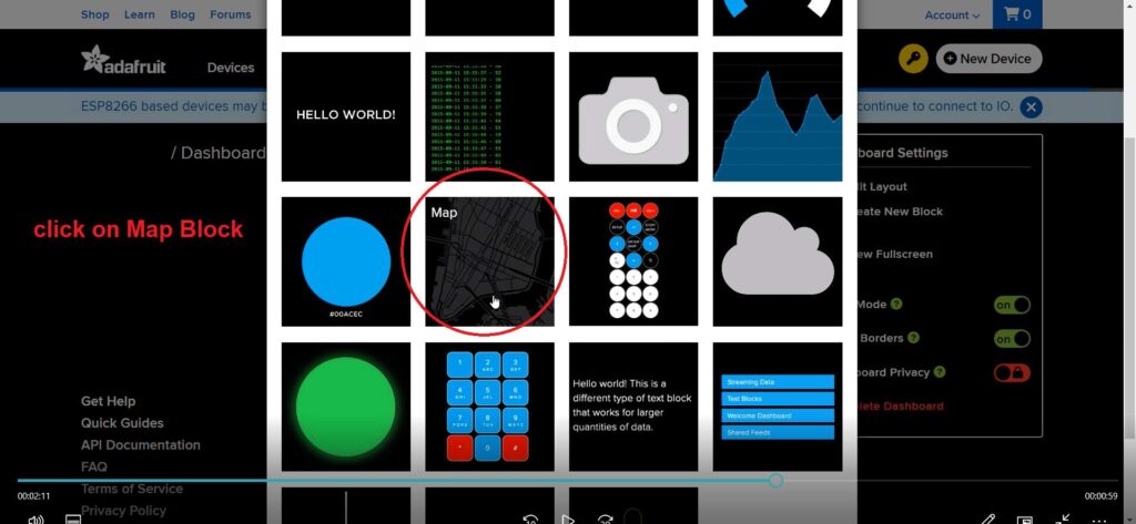
Now, you will see a variety of block options available. Each block type serves a different purpose, and you can choose one based on your specific needs. For this project, since we are dealing with GPS data, we will select the “Map Block” to display the location information. The Map Block will visually represent the GPS coordinates on a map, making it easier to monitor and understand the location data.
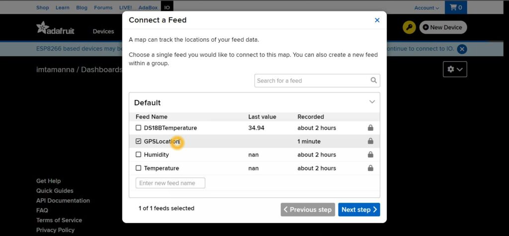
After clicking on the “Map Block,” a popup window will appear prompting you to set up the block. In this window, you will need to connect the block to the feed you previously created. Since our feed is named “GPSLocation,” you will select this feed from the list. This connection allows the Map Block to display the location data from your “GPSLocation” feed on the dashboard.
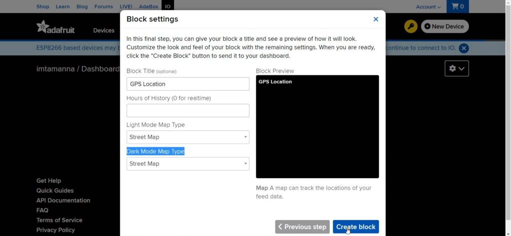
Next, click on “Next Step” to configure the layout of the block. In this step, you will need to provide a name for your layout, which will help you identify it on the dashboard. Additionally, you can choose between Light and Dark modes for the Map visualization, allowing you to customize the appearance based on your preference or the overall design of your dashboard. Once you’ve set these options, proceed to finalize the setup.
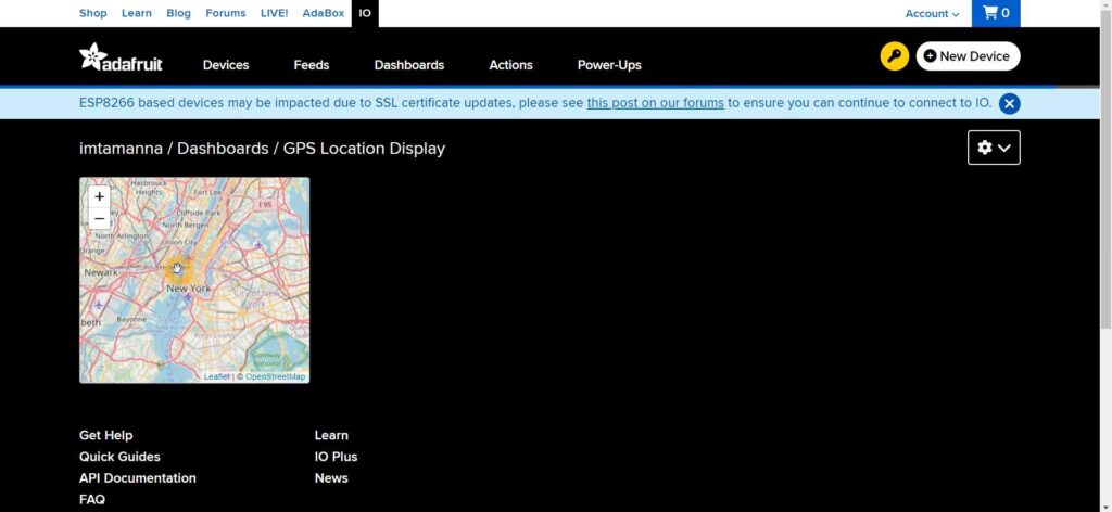
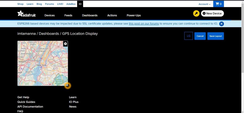
After clicking on “Create Block,” you will be redirected to your dashboard where the Map Block will now be displayed. The map will visually present the GPS data from your “GPSLocation” feed, allowing you to see the location information in real-time. This integration provides a clear and interactive way to monitor your GPS data directly from your Adafruit IO dashboard.
If you want to resize the map, click on the settings icon and then select “Edit Layout.” This will enable layout editing mode. To resize the map, click and hold one side of the map block and drag it to your desired size. Once you have adjusted the map to your preference, click “Save Layout” to apply and save your changes. This allows you to customize the display for optimal viewing on your dashboard.
Circuit Diagram
Circuit Explanation
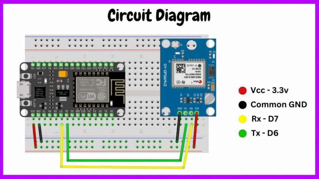
Based on the circuit diagram provided, the key components and connections are as follows:
- NodeMCU
- NEO 6M GPS
- The NodeMCU board interfaces with the GPS module using the following connections:
| NEO 6M GPS | NodeMCU |
| Rx (GPS) | D7 (NodeMCU Tx) |
| Tx (GPS) | D6 (NodeMCU Rx) |
| Vcc | 3.3V |
| GND | GND |
Power Supply:
The NodeMCU is powered:
- Via USB cable from a laptop.
- Optionally, you can use a 5V external power supply connected to Vin and GND on the NodeMCU board for standalone operation.
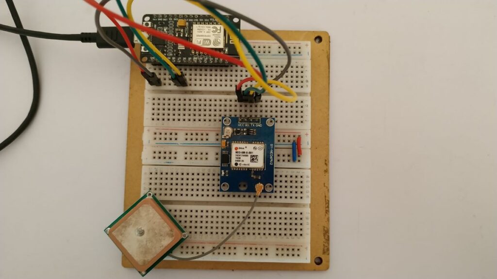
NodeMCU/ESP Circuit Setup
Source Code
#include <ESP8266WiFi.h>
#include <TinyGPSPlus.h>
#include <SoftwareSerial.h>
#include "Adafruit_MQTT.h"
#include "Adafruit_MQTT_Client.h"

static const int RXPin = 12, TXPin = 13;
static const uint32_t GPSBaud = 9600;

// The TinyGPSPlus object
TinyGPSPlus gps;

// The serial connection to the GPS device
SoftwareSerial softSerial(RXPin, TXPin);

// WiFi parameters
#define WLAN_SSID       "*****"
#define WLAN_PASS       "************"

// Adafruit IO
#define AIO_SERVER      "io.adafruit.com"
#define AIO_SERVERPORT  1883
//Enter the username and key from the Adafruit IO
#define AIO_USERNAME    "*******"
#define AIO_KEY         "****************************"
WiFiClient client;
// Setup the MQTT client class by passing in the WiFi client and MQTT server and login details.
Adafruit_MQTT_Client mqtt(&client, AIO_SERVER, AIO_SERVERPORT, AIO_USERNAME, AIO_KEY);
Adafruit_MQTT_Publish GPSLocation = Adafruit_MQTT_Publish(&mqtt, AIO_USERNAME "/feeds/GPSLocation/csv");

float speed_mph = 0;
float alltitude = 0;
float lati;     //Storing the Latitude
float longi;    //Storing the Longitude

char gpsdata[120];
void setup() {
  // put your setup code here, to run once:
  Serial.begin(115200);
  softSerial.begin(GPSBaud);

  Serial.print(F("Connecting to "));
  Serial.println(WLAN_SSID);
  WiFi.begin(WLAN_SSID, WLAN_PASS);
  while (WiFi.status() != WL_CONNECTED) {
    delay(500);
    Serial.print(F("."));
  }
  Serial.println();
  Serial.println(F("WiFi connected"));
  Serial.println(F("IP address: "));
  Serial.println(WiFi.localIP());

  // connect to adafruit io
  connect();
}

// connect to adafruit io via MQTT
void connect() {
  Serial.print(F("Connecting to Adafruit IO... "));
  int8_t ret;
  while ((ret = mqtt.connect()) != 0) {
    switch (ret) {
      case 1: Serial.println(F("Wrong protocol")); break;
      case 2: Serial.println(F("ID rejected")); break;
      case 3: Serial.println(F("Server unavail")); break;
      case 4: Serial.println(F("Bad user/pass")); break;
      case 5: Serial.println(F("Not authed")); break;
      case 6: Serial.println(F("Failed to subscribe")); break;
      default: Serial.println(F("Connection failed")); break;
    }

    if(ret >= 0)
      mqtt.disconnect();

    Serial.println(F("Retrying connection..."));
    delay(10000);
  }
  Serial.println(F("Adafruit IO Connected!"));
}

void loop() {
  // put your main code here, to run repeatedly:
if(! mqtt.ping(3)) {
    // reconnect to adafruit io
    if(! mqtt.connected())
      connect();
  }

  getCoordinates();

  Serial.print("Lati = ");
  Serial.print(lati,6);
  Serial.print("\tLongi = ");
  Serial.println(longi,6);

    if (!GPSLocation.publish(gpsdata)) {                     //Publish to Adafruit
      Serial.println(F("Failed"));
    }
    else {
      Serial.println(F("Sent!"));
    }
    delay(5000);
}


void getCoordinates()
{
   readGPSData();
  char *p = gpsdata;
  // add speed value
  dtostrf(speed_mph, 2, 6, p);
  p += strlen(p);
  p[0] = ','; p++;

  // concat latitude
  dtostrf(lati, 2, 6, p);
  p += strlen(p);
  p[0] = ','; p++;

  // concat longitude
  dtostrf(longi, 3, 6, p);
  p += strlen(p);
  p[0] = ','; p++;

  // concat altitude
  dtostrf(alltitude, 2, 6, p);
  p += strlen(p);

  // null terminate
  p[0] = 0;

}

void readGPSData()
{
  if(gps.location.isValid()){
    lati = gps.location.lat();
    longi = gps.location.lng();
    Serial.print("Lati: ");
    Serial.print(lati,6);
    Serial.print("\tLongi: ");
    Serial.println(longi,6);
  }
  waitGPS(1000);
  if (millis() > 5000 && gps.charsProcessed() < 10)
    Serial.println("Waiting for data...");
}

static void waitGPS(unsigned long ms)
{
  unsigned long start = millis();
  do
  {
    while (softSerial.available())
      gps.encode(softSerial.read());
  } while (millis() - start < ms);
}
Pingback: How to Interface Membrane Matrix Keypad Using Arduino Uno with Example Project - Projects4u
Pingback: Home Automation Project Using Raspberry Pi Pico Bluetooth - Projects4u
Pingback: Smart Digital Notice Board with NodeMCU ESP8266 - Projects4u