Introduction
We will learn how to integrate the Raspberry Pi Pico with the DHT11 humidity and temperature sensor in this tutorial. The DHT11 sensor will first have its MycroPython code written for it, which we will then integrate with the Raspberry Pi Pico to view the data in the serial monitor. Next, we’ll utilize a 0.96′′ I2C OLED to show the same temperature and humidity information on the screen.
The DHT11 is a cheap digital sensor for measuring temperature and humidity. The DHT11 sensor includes capacitive humidity and resistive temperature sensors. You can easily integrate this sensor using any of the digital input ports on an AVR ATMEGA16, Arduino, or Raspberry Pi Pico.
This article will walk you through integrating the DHT11 sensor with Raspberry Pi Pico. We will fetch the temperature and humidity data from the sensor and learn to code how to show that data on a 0.96′′ I2C OLED display.
Hardware Requirements
Notice: There might be affiliate links to Amazon on this page. which implies that I may receive a tiny commission from the sale. This may be your way of indirectly assisting me. Regards- Raspberry Pi Pico (HERE)
- Micro USB cable (HERE)
- 0.96″ I2C OLED Display (HERE)
- DHT11 Sensor (HERE)
- Connecting Wires (HERE)
- Small Breadboard (HERE)
Software Requirements
DHT11 Humidity & Temperature Sensor
DHT11 is a low-cost humidity and temperature sensor and uses a single-wire digital interface. Basically, it uses a capacitive humidity sensor and a thermistor to measure the temperature of the surrounding air. It can measure a temperature range of about 3.3 to 5 volts which is 0 to 50 degrees C with an accuracy of 2 degrees C and humidity of about 20% to 80% with an accuracy of 5%. The sensor makes use of single-wire communication which makes the sensor easy to interface with any of the microcontrollers.
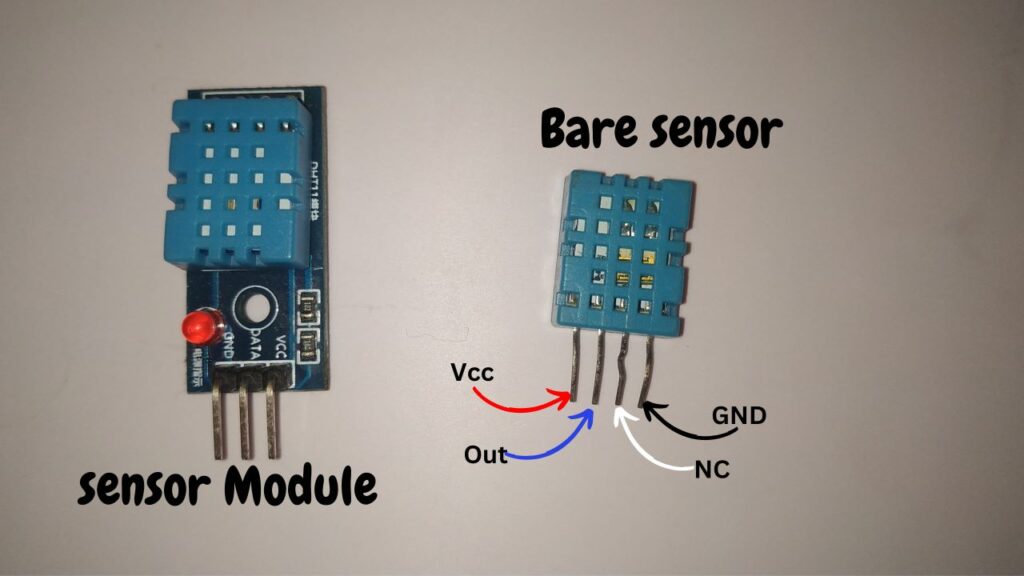
DHT11 has four pins known as VCC, GND, and DATA, and the fourth pin is not connected. So, the fourth pin was left unconnected.
In the local market, you can get a bare sensor with four pins and a sensor module. You can use any of the types, leaving the fourth pin unconnected. And make sure when you use a bare sensor you need to connect a pull-up resistor of 4.7K ohm at its DATA pin.
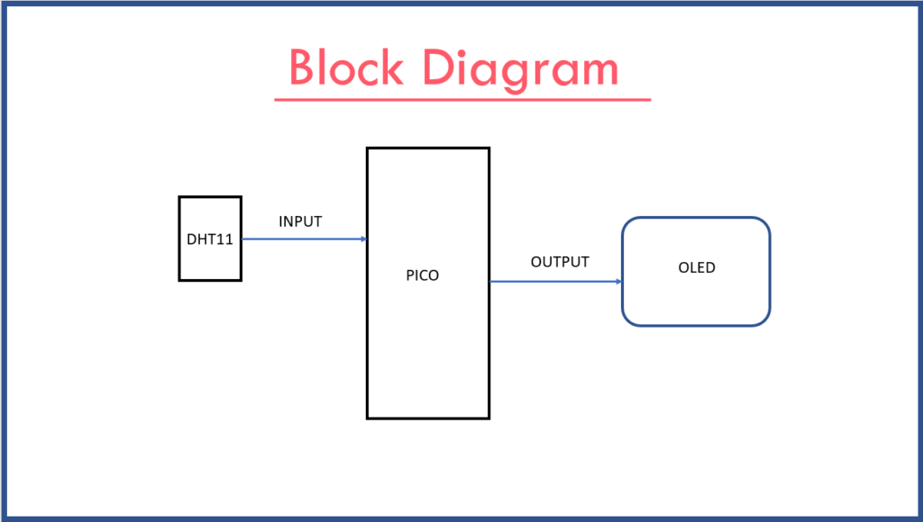
Block Diagram
Circuit Diagram
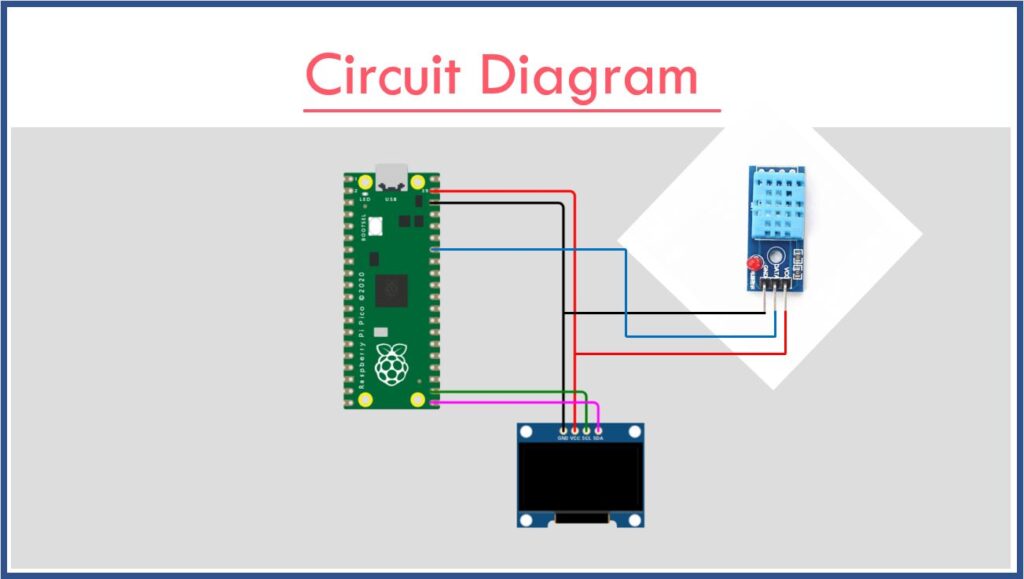
DHT11: To use the DHT11 sensor with the Raspberry Pi Pico, connect the sensor’s DATA pin to the Pico’s PIN GP28. Link the sensor’s VCC pin to the Pico’s VSYS pin and connect the sensor’s GND pin to the Pico’s GND pin. This setup allows the Pico to read temperature and humidity data from the DHT11 sensor.
OLED Display: To connect the OLED display to the Raspberry Pi Pico, attach the Pico’s GP17 pin to the display’s SCL pin and the Pico’s GP16 pin to the display’s SDA pin. Connect the display’s VCC pin to the Pico’s VSYS pin and the display’s GND pin to the Pico’s GND pin. This setup enables the Pico to communicate with the OLED display.
VSYS: VSYS provides the system voltage, allowing you to supply an external 5-volt input to the Raspberry Pi Pico. By connecting an external power source to VSYS, you ensure the board receives adequate power. The GND pin serves as the common ground for the entire board, providing a reference point for all voltage levels and completing the circuit.
Source Code
- DHT11 library code. (HERE)
- OLED display library code
- SSD1306 library code
- The main code
DHT11 Library Code: (dht.py)
Open Thony IDE create a new file in Thonny IDE then copy the below code and paste it into the new file. Then save it as dht.py file on the Raspberry Pi Pico board memory. This is the DHT library file which will help us to read the sensor data and provide us with temperature and humidity values.
import array
import micropython
import utime
from machine import Pin
from micropython import const

class InvalidChecksum(Exception):
    pass

class InvalidPulseCount(Exception):
    pass

MAX_UNCHANGED = const(100)
MIN_INTERVAL_US = const(200000)
HIGH_LEVEL = const(50)
EXPECTED_PULSES = const(84)

class DHT11:
    _temperature: float
    _humidity: float

    def __init__(self, pin):
        self._pin = pin
        self._last_measure = utime.ticks_us()
        self._temperature = -1
        self._humidity = -1

    def measure(self):
        current_ticks = utime.ticks_us()
        if utime.ticks_diff(current_ticks, self._last_measure) < MIN_INTERVAL_US and (
            self._temperature > -1 or self._humidity > -1
        ):
            # Less than a second since last read, which is too soon according
            # to the datasheet
            return

        self._send_init_signal()
        pulses = self._capture_pulses()
        buffer = self._convert_pulses_to_buffer(pulses)
        self._verify_checksum(buffer)

        self._humidity = buffer[0] + buffer[1] / 10
        self._temperature = buffer[2] + buffer[3] / 10
        self._last_measure = utime.ticks_us()

    @property
    def humidity(self):
        self.measure()
        return self._humidity

    @property
    def temperature(self):
        self.measure()
        return self._temperature

    def _send_init_signal(self):
        self._pin.init(Pin.OUT, Pin.PULL_DOWN)
        self._pin.value(1)
        utime.sleep_ms(50)
        self._pin.value(0)
        utime.sleep_ms(18)

    @micropython.native
    def _capture_pulses(self):
        pin = self._pin
        pin.init(Pin.IN, Pin.PULL_UP)

        val = 1
        idx = 0
        transitions = bytearray(EXPECTED_PULSES)
        unchanged = 0
        timestamp = utime.ticks_us()

        while unchanged < MAX_UNCHANGED:
            if val != pin.value():
                if idx >= EXPECTED_PULSES:
                    raise InvalidPulseCount(
                        "Got more than {} pulses".format(EXPECTED_PULSES)
                    )
                now = utime.ticks_us()
                transitions[idx] = now - timestamp
                timestamp = now
                idx += 1

                val = 1 - val
                unchanged = 0
            else:
                unchanged += 1
        pin.init(Pin.OUT, Pin.PULL_DOWN)
        if idx != EXPECTED_PULSES:
            raise InvalidPulseCount(
                "Expected {} but got {} pulses".format(EXPECTED_PULSES, idx)
            )
        return transitions[4:]

    def _convert_pulses_to_buffer(self, pulses):
        """Convert a list of 80 pulses into a 5 byte buffer
        The resulting 5 bytes in the buffer will be:
            0: Integral relative humidity data
            1: Decimal relative humidity data
            2: Integral temperature data
            3: Decimal temperature data
            4: Checksum
        """
        # Convert the pulses to 40 bits
        binary = 0
        for idx in range(0, len(pulses), 2):
            binary = binary << 1 | int(pulses[idx] > HIGH_LEVEL)

        # Split into 5 bytes
        buffer = array.array("B")
        for shift in range(4, -1, -1):
            buffer.append(binary >> shift * 8 & 0xFF)
        return buffer

    def _verify_checksum(self, buffer):
        # Calculate checksum
        checksum = 0
        for buf in buffer[0:4]:
            checksum += buf
        if checksum & 0xFF != buffer[4]:
            raise InvalidChecksum()
OLED library code:
To install the OLED library follow the steps. In Thonny IDE go to Tools-> Manage Packages-> search “oled” for the library find the “micropython-oled” library from the search items by the author: Yeison Cardona and you can find an Install button below, just click and install it. We will install it inside the Raspberry Pi Pico.
SSD1306 library code:(ssd1306.py)
Open Thony IDE and create a new file, copy the below code, and paste it into the new file after that save the file as a ssd1306.py file in the Raspberry Pi Pico board memory. This is the SSD1306 library file and we will use it to display messages.
import time
# import framebuf
try:
    import framebuf
except:
    def const(x): return x


# register definitions
SET_CONTRAST = const(0x81)
SET_ENTIRE_ON = const(0xa4)
SET_NORM_INV = const(0xa6)
SET_DISP = const(0xae)
SET_MEM_ADDR = const(0x20)
SET_COL_ADDR = const(0x21)
SET_PAGE_ADDR = const(0x22)
SET_DISP_START_LINE = const(0x40)
SET_SEG_REMAP = const(0xa0)
SET_MUX_RATIO = const(0xa8)
SET_COM_OUT_DIR = const(0xc0)
SET_DISP_OFFSET = const(0xd3)
SET_COM_PIN_CFG = const(0xda)
SET_DISP_CLK_DIV = const(0xd5)
SET_PRECHARGE = const(0xd9)
SET_VCOM_DESEL = const(0xdb)
SET_CHARGE_PUMP = const(0x8d)


class SSD1306:
    def __init__(self, width, height, external_vcc):
        self.width = width
        self.height = height
        self.external_vcc = external_vcc
        self.pages = self.height // 8
        # Note the subclass must initialize self.framebuf to a framebuffer.
        # This is necessary because the underlying data buffer is different
        # between I2C and SPI implementations (I2C needs an extra byte).
        self.poweron()
        self.init_display()

    def init_display(self):
        for cmd in (
            SET_DISP | 0x00,  # off
            # address setting
            SET_MEM_ADDR, 0x00,  # horizontal
            # resolution and layout
            SET_DISP_START_LINE | 0x00,
            SET_SEG_REMAP | 0x01,  # column addr 127 mapped to SEG0
            SET_MUX_RATIO, self.height - 1,
            SET_COM_OUT_DIR | 0x08,  # scan from COM[N] to COM0
            SET_DISP_OFFSET, 0x00,
            SET_COM_PIN_CFG, 0x02 if self.height == 32 else 0x12,
            # timing and driving scheme
            SET_DISP_CLK_DIV, 0x80,
            SET_PRECHARGE, 0x22 if self.external_vcc else 0xf1,
            SET_VCOM_DESEL, 0x30,  # 0.83*Vcc
            # display
            SET_CONTRAST, 0xff,  # maximum
            SET_ENTIRE_ON,  # output follows RAM contents
            SET_NORM_INV,  # not inverted
            # charge pump
            SET_CHARGE_PUMP, 0x10 if self.external_vcc else 0x14,
                SET_DISP | 0x01):  # on
            self.write_cmd(cmd)
        self.fill(0)
        self.show()

    def poweroff(self):
        self.write_cmd(SET_DISP | 0x00)

    def contrast(self, contrast):
        self.write_cmd(SET_CONTRAST)
        self.write_cmd(contrast)

    def invert(self, invert):
        self.write_cmd(SET_NORM_INV | (invert & 1))

    def show(self):
        x0 = 0
        x1 = self.width - 1
        if self.width == 64:
            # displays with width of 64 pixels are shifted by 32
            x0 += 32
            x1 += 32
        self.write_cmd(SET_COL_ADDR)
        self.write_cmd(x0)
        self.write_cmd(x1)
        self.write_cmd(SET_PAGE_ADDR)
        self.write_cmd(0)
        self.write_cmd(self.pages - 1)
        self.write_framebuf()

    def fill(self, col):
        self.framebuf.fill(col)

    def pixel(self, x, y, col):
        self.framebuf.pixel(x, y, col)

    def scroll(self, dx, dy):
        self.framebuf.scroll(dx, dy)

    def text(self, string, x, y, col=1):
        self.framebuf.text(string, x, y, col)


class SSD1306_I2C(SSD1306):
    def __init__(self, width, height, i2c, addr=0x3c, external_vcc=False):
        self.i2c = i2c
        self.addr = addr
        self.temp = bytearray(2)
        # Add an extra byte to the data buffer to hold an I2C data/command byte
        # to use hardware-compatible I2C transactions.  A memoryview of the
        # buffer is used to mask this byte from the framebuffer operations
        # (without a major memory hit as memoryview doesn't copy to a separate
        # buffer).
        self.buffer = bytearray(((height // 8) * width) + 1)
        self.buffer[0] = 0x40  # Set first byte of data buffer to Co=0, D/C=1
        self.framebuf = framebuf.FrameBuffer1(memoryview(self.buffer)[1:], width, height)
        super().__init__(width, height, external_vcc)

    def write_cmd(self, cmd):
        self.temp[0] = 0x80  # Co=1, D/C#=0
        self.temp[1] = cmd
        self.i2c.writeto(self.addr, self.temp)

    def write_framebuf(self):
        # Blast out the frame buffer using a single I2C transaction to support
        # hardware I2C interfaces.
        self.i2c.writeto(self.addr, self.buffer)

    def poweron(self):
        pass


class SSD1306_SPI(SSD1306):
    def __init__(self, width, height, spi, dc, res, cs, external_vcc=False):
        self.rate = 10 * 1024 * 1024
        dc.init(dc.OUT, value=0)
        res.init(res.OUT, value=0)
        cs.init(cs.OUT, value=1)
        self.spi = spi
        self.dc = dc
        self.res = res
        self.cs = cs
        self.buffer = bytearray((height // 8) * width)
        self.framebuf = framebuf.FrameBuffer1(self.buffer, width, height)
        super().__init__(width, height, external_vcc)

    def write_cmd(self, cmd):
        self.spi.init(baudrate=self.rate, polarity=0, phase=0)
        self.cs.high()
        self.dc.low()
        self.cs.low()
        self.spi.write(bytearray([cmd]))
        self.cs.high()

    def write_framebuf(self):
        self.spi.init(baudrate=self.rate, polarity=0, phase=0)
        self.cs.high()
        self.dc.high()
        self.cs.low()
        self.spi.write(self.buffer)
        self.cs.high()

    def poweron(self):
        self.res.high()
        time.sleep_ms(1)
        self.res.low()
        time.sleep_ms(10)
        self.res.high()
Main Code: (main.py)
Here is the final code that fetches sensor data and displays it on the OLED display. To proceed, create a new file in the Thonny IDE. Next, copy and paste the code from the download section, named mainCode.txt. Save this file as main.py on the Raspberry Pi Pico board.
Why the main.py file name?
You can choose any name for the file. If you run the code from the Thonny IDE by clicking the green button at the top of the IDE, it will execute only once. In contrast, naming the file main.py allows the Raspberry Pi Pico board to automatically detect and run the code every time it starts up. This feature is known as the AutoStart system.
from machine import Pin, I2C
from ssd1306 import SSD1306_I2C
from oled import Write, GFX, SSD1306_I2C
from oled.fonts import ubuntu_mono_15, ubuntu_mono_20
import utime as time
from dht import DHT11

WIDTH  = 128                                            # oled display width
HEIGHT = 64                                             # oled display height

i2c = I2C(0, scl=Pin(17), sda=Pin(16), freq=200000)       # Init I2C using pins GP8 & GP9 (default I2C0 pins)

display = SSD1306_I2C(WIDTH, HEIGHT, i2c)                  # Init oled display
fontSize20 = Write(display, ubuntu_mono_20)

while True:
    time.sleep(1)
    pin = Pin(28, Pin.OUT, Pin.PULL_DOWN)
    sensor = DHT11(pin)
    t  = (sensor.temperature)
    h = (sensor.humidity)
    # Clear the oled display in case it has junk on it.
    display.fill(0)
    fontSize20.text("DHT11", 40, 0)

    # Add some text
    display.text("Temp: ",15,30)
    display.text(str(sensor.temperature),60,30)
    display.pixel(98,31,30)
    display.pixel(98,30,30)
    display.pixel(99,30,30)
    display.pixel(99,31,30)
    display.text("C",100,30)

    display.text("Humi: ",15,50)
    display.text(str(sensor.humidity),60,50)
    display.text("%",100,50)

    time.sleep(1)
    display.show()