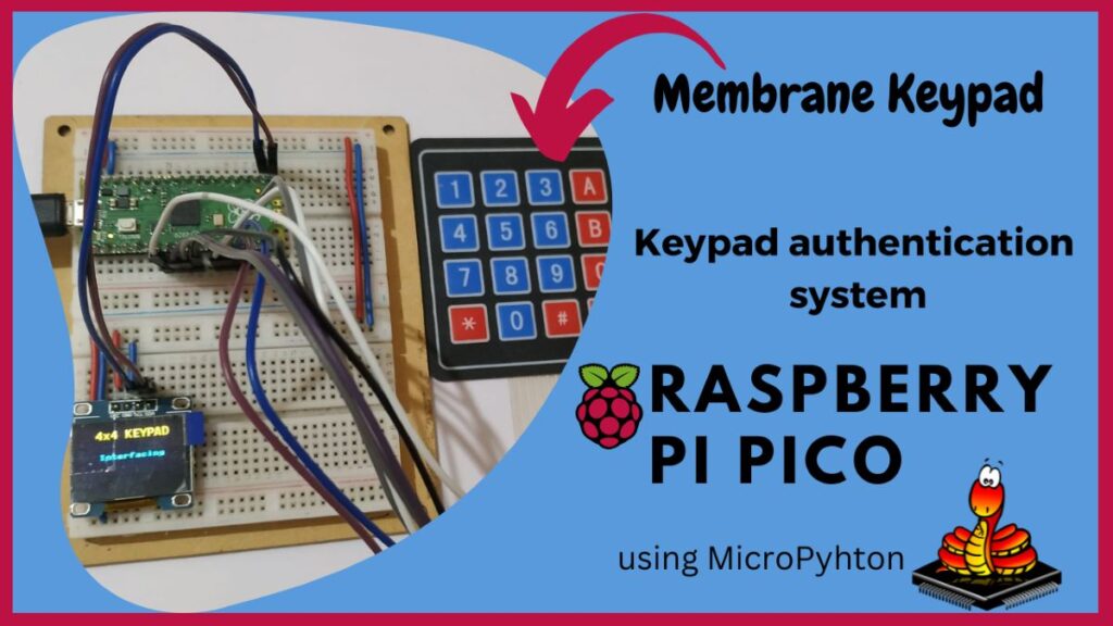
Introduction
The Raspberry Pi Pico, a powerful and versatile microcontroller, offers an excellent platform for developing various projects, including security systems. One such project is creating a keypad integration and authentication system. This project demonstrates how to interface a keypad with the Raspberry Pi Pico to enable secure access control. By using a keypad, users can input a password or PIN, which the system then verifies to grant or deny access. This setup is ideal for applications such as secure entry points, electronic locks, and other security-sensitive environments.
The process involves connecting the keypad to the Pico, writing the code to handle input and verification, and implementing security measures to protect against unauthorized access. This guide provides step-by-step instructions, making it accessible for beginners and experienced hobbyists alike. By the end of this project, you will have a fully functional keypad-based authentication system, enhancing both your knowledge and security capabilities.
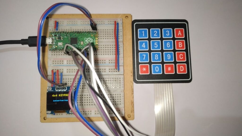
Once you have completed learning about the 4×4 keypad and SSD1306 OLED display, we will learn the integration process of 4×4 keypad and SSD1306 display then we will start building the project.
After the desired key pressed, the system quickly verifies the key pushed and stores the data in an array. After that it compares this information with the hardcoded password to determine whether to grant the user’s authentication or deny it.
Hardware Requirements
Notice: There might be affiliate links to Amazon on this page. which implies that I may receive a tiny commission from the sale. This may be your way of indirectly assisting me. Regards- Raspberry Pi Pico Board (HERE)
- Micro-USB Cable (HERE)
- 4×4 Membrane Keypad (HERE)
- Small Breadboard (HERE)
- Connecting Wires (HERE)
Software Requirements
About Membrane Keypad
A 4×4 membrane keypad serves as a compact and flexible input device, frequently used in embedded systems and microcontroller projects. It features 16 keys arranged in a 4-row by 4-column matrix, allowing users to input numbers, letters, or commands. Constructed with a thin, flexible membrane overlaying conductive traces, the keypad remains lightweight and durable. Users find the design user-friendly, with clearly labeled buttons that provide tactile feedback when pressed, ensuring reliable and accurate data entry.
DIY electronics enthusiasts and educators often choose the 4×4 membrane keypad due to its simplicity and ease of integration. You can connect it to a microcontroller using a straightforward matrix scanning method, which scans rows and columns to detect key presses. This efficient interfacing method reduces the number of required input/output pins, making it ideal for microcontrollers with limited I/O availability. Whether you use it in security systems, calculators, or interactive displays, the 4×4 membrane keypad offers a versatile and reliable solution for user input.
About SSD1306 OLED Display
The SSD1306 OLED display is a popular choice among hobbyists and professionals for its clear, high-contrast visuals and efficient power consumption. This compact display, typically available in sizes like 0.96 and 1.3 inches, features a resolution of 128×64 pixels. You can connect it to microcontrollers using I2C or SPI interfaces, making it highly versatile for various projects. The OLED technology ensures bright and sharp images without the need for backlighting, which reduces power usage and extends the lifespan of portable devices.
You can use the SSD1306 OLED display in numerous applications, from simple text displays to complex graphical interfaces. Its wide viewing angle and quick response time make it ideal for projects requiring real-time data visualization, such as weather stations, digital clocks, and IoT devices. The display’s compact size and low power requirements make it an excellent choice for battery-operated projects. Whether you are displaying sensor data or creating interactive interfaces, the SSD1306 OLED display provides a reliable and visually appealing solution.
Pin Out of SSD1306 display
| SSD1306 OLED | Description |
| VCC | 3.3v – 5v |
| GND | Common Ground |
| SCK | Serial Clock |
| SDA | Serial Data |
Circuit Diagram
Circuit Explanation
Follow the table below to build your circuit. Connect the components as shown, ensuring each connection matches the diagram. Double-check your wiring and component placement for accuracy. Power up the circuit and test its functionality to ensure it operates as intended. Make adjustments if necessary.
| 4×4 Membrane Keypad | Raspberry Pi Pico |
| COL1 | GP6 |
| COL2 | GP7 |
| COL3 | GP8 |
| COL4 | GP9 |
| ROW1 | GP10 |
| ROW2 | GP11 |
| ROW3 | GP12 |
| ROW4 | GP13 |
Source Code
- OLED display library code.
- SSD1306 library (HERE)
- The main code
OLED library code:
To install oled library follow the steps. In Thonny IDE go to Tools-> Manage Packages-> search “oled” for the library find the “micropython-oled” library from the search items by the author: Yeison Cardona and you can find an Install button below, just click and install it. It will be installed inside the Raspberry Pi Pico. So, no need to check, It will work.
SSD1306 library:
Open Thony IDE and create a new file in, copy the below code and paste it in the new file after that save the file as a ssd1306.py file in the Raspberry Pi Pico board memory. This is the SSD1306 library file and we will use it to display messages.
import time
# import framebuf
try:
    import framebuf
except:
    def const(x): return x


# register definitions
SET_CONTRAST = const(0x81)
SET_ENTIRE_ON = const(0xa4)
SET_NORM_INV = const(0xa6)
SET_DISP = const(0xae)
SET_MEM_ADDR = const(0x20)
SET_COL_ADDR = const(0x21)
SET_PAGE_ADDR = const(0x22)
SET_DISP_START_LINE = const(0x40)
SET_SEG_REMAP = const(0xa0)
SET_MUX_RATIO = const(0xa8)
SET_COM_OUT_DIR = const(0xc0)
SET_DISP_OFFSET = const(0xd3)
SET_COM_PIN_CFG = const(0xda)
SET_DISP_CLK_DIV = const(0xd5)
SET_PRECHARGE = const(0xd9)
SET_VCOM_DESEL = const(0xdb)
SET_CHARGE_PUMP = const(0x8d)


class SSD1306:
    def __init__(self, width, height, external_vcc):
        self.width = width
        self.height = height
        self.external_vcc = external_vcc
        self.pages = self.height // 8
        # Note the subclass must initialize self.framebuf to a framebuffer.
        # This is necessary because the underlying data buffer is different
        # between I2C and SPI implementations (I2C needs an extra byte).
        self.poweron()
        self.init_display()

    def init_display(self):
        for cmd in (
            SET_DISP | 0x00,  # off
            # address setting
            SET_MEM_ADDR, 0x00,  # horizontal
            # resolution and layout
            SET_DISP_START_LINE | 0x00,
            SET_SEG_REMAP | 0x01,  # column addr 127 mapped to SEG0
            SET_MUX_RATIO, self.height - 1,
            SET_COM_OUT_DIR | 0x08,  # scan from COM[N] to COM0
            SET_DISP_OFFSET, 0x00,
            SET_COM_PIN_CFG, 0x02 if self.height == 32 else 0x12,
            # timing and driving scheme
            SET_DISP_CLK_DIV, 0x80,
            SET_PRECHARGE, 0x22 if self.external_vcc else 0xf1,
            SET_VCOM_DESEL, 0x30,  # 0.83*Vcc
            # display
            SET_CONTRAST, 0xff,  # maximum
            SET_ENTIRE_ON,  # output follows RAM contents
            SET_NORM_INV,  # not inverted
            # charge pump
            SET_CHARGE_PUMP, 0x10 if self.external_vcc else 0x14,
                SET_DISP | 0x01):  # on
            self.write_cmd(cmd)
        self.fill(0)
        self.show()

    def poweroff(self):
        self.write_cmd(SET_DISP | 0x00)

    def contrast(self, contrast):
        self.write_cmd(SET_CONTRAST)
        self.write_cmd(contrast)

    def invert(self, invert):
        self.write_cmd(SET_NORM_INV | (invert & 1))

    def show(self):
        x0 = 0
        x1 = self.width - 1
        if self.width == 64:
            # displays with width of 64 pixels are shifted by 32
            x0 += 32
            x1 += 32
        self.write_cmd(SET_COL_ADDR)
        self.write_cmd(x0)
        self.write_cmd(x1)
        self.write_cmd(SET_PAGE_ADDR)
        self.write_cmd(0)
        self.write_cmd(self.pages - 1)
        self.write_framebuf()

    def fill(self, col):
        self.framebuf.fill(col)

    def pixel(self, x, y, col):
        self.framebuf.pixel(x, y, col)

    def scroll(self, dx, dy):
        self.framebuf.scroll(dx, dy)

    def text(self, string, x, y, col=1):
        self.framebuf.text(string, x, y, col)


class SSD1306_I2C(SSD1306):
    def __init__(self, width, height, i2c, addr=0x3c, external_vcc=False):
        self.i2c = i2c
        self.addr = addr
        self.temp = bytearray(2)
        # Add an extra byte to the data buffer to hold an I2C data/command byte
        # to use hardware-compatible I2C transactions.  A memoryview of the
        # buffer is used to mask this byte from the framebuffer operations
        # (without a major memory hit as memoryview doesn't copy to a separate
        # buffer).
        self.buffer = bytearray(((height // 8) * width) + 1)
        self.buffer[0] = 0x40  # Set first byte of data buffer to Co=0, D/C=1
        self.framebuf = framebuf.FrameBuffer1(memoryview(self.buffer)[1:], width, height)
        super().__init__(width, height, external_vcc)

    def write_cmd(self, cmd):
        self.temp[0] = 0x80  # Co=1, D/C#=0
        self.temp[1] = cmd
        self.i2c.writeto(self.addr, self.temp)

    def write_framebuf(self):
        # Blast out the frame buffer using a single I2C transaction to support
        # hardware I2C interfaces.
        self.i2c.writeto(self.addr, self.buffer)

    def poweron(self):
        pass


class SSD1306_SPI(SSD1306):
    def __init__(self, width, height, spi, dc, res, cs, external_vcc=False):
        self.rate = 10 * 1024 * 1024
        dc.init(dc.OUT, value=0)
        res.init(res.OUT, value=0)
        cs.init(cs.OUT, value=1)
        self.spi = spi
        self.dc = dc
        self.res = res
        self.cs = cs
        self.buffer = bytearray((height // 8) * width)
        self.framebuf = framebuf.FrameBuffer1(self.buffer, width, height)
        super().__init__(width, height, external_vcc)

    def write_cmd(self, cmd):
        self.spi.init(baudrate=self.rate, polarity=0, phase=0)
        self.cs.high()
        self.dc.low()
        self.cs.low()
        self.spi.write(bytearray([cmd]))
        self.cs.high()

    def write_framebuf(self):
        self.spi.init(baudrate=self.rate, polarity=0, phase=0)
        self.cs.high()
        self.dc.high()
        self.cs.low()
        self.spi.write(self.buffer)
        self.cs.high()

    def poweron(self):
        self.res.high()
        time.sleep_ms(1)
        self.res.low()
        time.sleep_ms(10)
        self.res.high()
The Main Source Code:
This is the final code which is responsible for the project, which detects the key pressed and displays them in OLED. And also verify the hardcoded password. Now create a new file in Thony IDE. Then copy the below code and paste it in the new file. After that save the file as main.py so that the code will run automatically whenever Raspberry Pi Pico bootup in the Raspberry Pi Pico board memory.
from machine import Pin, I2C
from ssd1306 import SSD1306_I2C
from oled import Write, GFX, SSD1306_I2C
from oled.fonts import ubuntu_mono_15, ubuntu_mono_20
import utime

WIDTH = 128
HEIGHT = 64
loc = 25
new_loc = 0

i2c = I2C(0, scl = Pin(17), sda = Pin(16), freq=200000)
display = SSD1306_I2C(WIDTH, HEIGHT, i2c)

# Create a map between keypad buttons and characters

keyPad = [['1', '2', '3', 'A'],
               ['4', '5', '6', 'B'],
               ['7', '8', '9', 'C'],
               ['*', '0', '#', 'D']]

# Define PINs according to cabling
rowPins = [13,12,11,10]
colPins = [9,8,7,6]


colValue = []
rowValue = []


password = []

oriPassword = ['1','2','3','5','8','0']

led = Pin(25, Pin.OUT, Pin.PULL_UP)
fontSize15 = Write(display, ubuntu_mono_15)
fontSize20 = Write(display, ubuntu_mono_20)

for i in range(0,4):
    rowValue.append(Pin(rowPins[i], Pin.OUT))
    rowValue[i].value(1)
    colValue.append(Pin(colPins[i], Pin.IN, Pin.PULL_DOWN))
    colValue[i].value(0)

def checkKeyPress():
    global loc
    for row in range(4):
        for col in range(4):
            rowValue[row].high()
            key = None
            if colValue[col].value() == 1:
                print("Key Pressed:", keyPad[row][col])
                fontSize20.text("*", loc, 50)
                display.show()
                key_press = keyPad[row][col]
                utime.sleep(0.3)
                password.append(key_press)
                loc = loc + 15
                print("Key Loc:", loc)
            if len(password) == 6:
                loc = 25
                checkPassword(password)
                for x in range(0,6):
                    password.pop()

        rowValue[row].low()

def displayDefault():
    display.fill(0)
    fontSize20.text("4x4 KEYPAD", 20, 0)
    display.text("Interfacing", 25, 35)
    display.show()

def checkPassword(password):
    if password == oriPassword:
        display.fill(0)
        fontSize20.text("Access",30,20)
        fontSize20.text("Accepted",22,40)
        display.show()
        print("Success! Correct Password")
        led.value(1)
        utime.sleep(5)
        led.value(0)
        displayDefault()
    else:
        display.fill(0)
        fontSize20.text("Access",30,20)
        fontSize20.text("Denied",30,40)
        display.show()
        print("Sorry! Incorrect Password")
        utime.sleep(5)
        displayDefault()

print("Please enter password")

displayDefault()
while True:
    checkKeyPress()